Help medical research with folding@home

Did you know: the first machine to break the exaflop barrier (one quintillion floating‑point operations per second) wasn’t a huge dedicated IBM supercomputer, but a bunch of interconnected PCs with ordinary CPUs and gaming GPUs.

With that in mind, welcome to the Folding@home project, which is targeting its enormous power at COVID-19 research. It’s effectively the world’s fastest supercomputer, and your PC can be a part of it.

COVID-19

The Folding@home project is now targeting COVID-19 research

Folding@home with Custom PC

Put simply, Folding@home runs hugely complicated simulations of protein molecules for medical research. They would usually take hundreds of years for a typical computer to process. However, by breaking them up into smaller work units, and farming them out to thousands of independent machines on the Internet, it’s possible to run simulations that would be impossible to run experimentally.

Back in 2004, Custom PC magazine started its own Folding@home team. The team is currently sitting at number 12 on the world leaderboard and we’re still going strong. If you have a PC, you can join us (or indeed any Folding@home team) and put your spare clock cycles towards COVID-19 research.

Get folding

Getting your machine folding is simple. First, download the client. Your username can be whatever you like, and you’ll need to put in team number 35947 to fold for the Custom PC & bit-tech team. If you want your PC to work on COVID-19 research, select ‘COVID-19’ in the ‘I support research finding’ pulldown menu.

Set your username and team number

Enter team number 35947 to fold for the Custom PC & bit-tech team

You’ll get the most points per Watt from GPU folding, but your CPU can also perform valuable research that can’t be done on your GPU. ‘There are actually some things we can do on CPUs that we can’t do on GPUs,’ said Professor Greg Bowman, Director of Folding@home, speaking to Custom PC in the latest issue.

‘With the current pandemic in mind, one of the things we’re doing is what are called “free energy calculations”. We’re simulating proteins with small molecules that we think might be useful starting points for developing therapeutics, for example.’

Select COVID-19 from the pulldown menu

If you want your PC to work on COVID-19 research, select ‘COVID-19’ in the ‘I support research finding’ pulldown menu

Bear in mind that enabling folding on your machine will increase power consumption. For reference, we set up folding on a Ryzen 7 2700X rig with a GeForce GTX 1070 Ti. The machine consumes around 70W when idle. That figure increases to 214W when folding on the CPU and around 320W when folding on the GPU as well. If you fold a lot, you’ll see an increase in your electricity bill, so keep an eye on it.

Folding on Arm?

Could we also see Folding@home running on Arm machines, such as Raspberry Pi? ‘Oh I would love to have Folding@home running on Arm,’ says Bowman. ‘I mean they’re used in Raspberry Pis and lots of phones, so I think this would be a great future direction. We’re actually in contact with some folks to explore getting Folding@home running on Arm in the near future.’

In the meantime, you can still recruit your Raspberry Pi for the cause by participating in Rosetta@home, a similar project also working to help the fight against COVID-19. For more information, visit the Rosetta@home website.

You’ll also find a full feature about Folding@home and its COVID-19 research in Issue 202 of Custom PC, available from the Raspberry Pi Press online store.

The post Help medical research with folding@home appeared first on Raspberry Pi.


Source: Raspberry Pi – Help medical research with folding@home

Making the best of it: online learning and remote teaching

As many educators across the world are currently faced with implementing some form of remote teaching during school closures, we thought this topic was ideal for the very first of our seminar series about computing education research.

Image by Mudassar Iqbal from Pixabay

Research into online learning and remote teaching

At the Raspberry Pi Foundation, we are hosting a free online seminar every second Tuesday to explore a wide variety of topics in the area of digital and computing education. Last Tuesday we were delighted to welcome Dr Lauren Margulieux, Assistant Professor of Learning Sciences at Georgia State University, USA. She shared her findings about different remote teaching approaches and practical tips for educators in the current crisis.

Lauren’s research interests are in educational technology and online learning, particularly for computing education. She focuses on designing instructions in a way that supports online students who do not necessarily have immediate access to a teacher or instructor to ask questions or overcome problem-solving impasses.

A vocabulary for online and blended learning

In non-pandemic situations, online instruction comes in many forms to serve many purposes, both in higher education and in K-12 (primary and secondary school). Much research has been carried out in how online learning can be used for successful learning outcomes, and in particular, how it can be blended with face-to-face (hybrid learning) to maximise the impact of both contexts.

In her seminar talk, Lauren helped us to understand the different ways in which online learning can take place, by sharing with us vocabulary to better describe different ways of learning with and through technology.

Lauren presented a taxonomy for classifying types of online and blended teaching and learning in two dimensions (shown in the image below). These are delivery type (technology or instructor), and whether content is received by learners, or actually being applied in the learning experience.

Lauren Margulieux seminar slide showing her taxonomy for different types of mixed student instruction

In Lauren’s words: “The taxonomy represents the four things that we control as instructors. We can’t control whether our students talk to each other or email each other, or ask each other questions […], therefore this taxonomy gives us a tool for defining how we design our classes.”

This taxonomy illustrates that there are a number of different ways in which the four types of instruction — instructor-transmitted, instructor-mediated, technology-transmitted, and technology-mediated — can be combined in a learning experience that uses both online and face-to-face elements.

Using her taxonomy in an examination (meta-analysis) of 49 studies relating to computer science teaching in higher education, Lauren found a range of different ways of mixing instruction, which are shown in the graph below.

  • Lecture hybrid means that the teaching is all delivered by the teacher, partly face-to-face and partly online.
  • Practice hybrid means that the learning is done through application of content and receiving feedback, which happens partly face-to-face or synchronously and partly online or asynchronously.
  • Replacement blend refers to instruction where lecture and practice takes place in a classroom and part of both is replaced with an online element.
  • Flipped blend instruction is where the content is transmitted through the use of technology, and the application of the learning is supported through an instructor. Again, the latter element can also take place online, but it is synchronous rather than asynchronous — as is the case in our current context.
  • Supplemental blend learning refers to instruction where content is delivered face-to-face, and then practice and application of content, together with feedback, takes place online — basically the opposite of the flipped blend approach.

Lauren Margulieux seminar slide showing learning outcomes of different types of mixed student instruction

Lauren’s examination found that the flipped blend approach was most likely to demonstrate improved learning outcomes. This is a useful finding for the many schools (and universities) that are experimenting with a range of different approaches to remote teaching.

Another finding of Lauren’s study was that approaches that involve the giving of feedback promoted improved learning. This has also been found in studies of assessment for learning, most notably by Black and Wiliam. As Lauren pointed out, the implication is that the reason blended and flipped learning approaches are the most impactful is that they include face-to-face or synchronous time for the educator to discuss learning with the students, including giving feedback.

Lauren’s tips for remote teaching

Of course we currently find ourselves in the midst of school closures across the world, so our only option in these circumstances is to teach online. In her seminar talk, Lauren also included some tips from her own experience to help educators trying to support their students during the current crisis:

  • Align learning objectives, instruction, activities, assignments, and assessments.
  • Use good equipment: headphones to avoid echo and a good microphone to improve clarity and reduce background noise.
  • Be consistent in disseminating information, as there is a higher barrier to asking questions.
  • Highlight important points verbally and visually.
  • Create ways for students to talk with each other, through discussions, breakout rooms, opportunities to talk when you aren’t present, etc.
  • Use video when possible while talking with your students.
    Give feedback frequently, even if only very brief.

Although Lauren’s experience is primarily from higher education (post-18), this advice is also useful for K-12 educators.

What about digital equity and inclusion?

All our seminars include an opportunity to break out into small discussion groups, followed by an opportunity to ask questions of the speaker. We had an animated follow-up discussion with Lauren, with many questions focused on issues of representation and inclusion. Some questions related to the digital divide and how we could support learners who didn’t have access to the technology they need. There were also questions from breakout groups about the participation of groups that are typically under-represented in computing education in online learning experiences, and accessibility for those with special educational needs and disabilities (SEND). While there is more work needed in this area, there’s also no one-size-fits-all approach to working with students with special needs, whether that’s due to SEND or to material resources (e.g. access to technology). What works for one student based on their needs might be entirely ineffective for others. Overall, the group concluded that there was a need for much more research in these areas, particularly at K-12 level.

Much anxiety has been expressed in the media, and more formally through bodies such as the World Economic Forum and UNESCO, about the potential long-lasting educational impact of the current period of school closures on disadvantaged students and communities. Research into the most inclusive way of supporting students through remote teaching will help here, as will the efforts of governments, charities, and philanthropists to provide access to technology to learners in need.

At the Raspberry Pi Foundation, we offer lots of free resources for students, educators, and parents to help them engage with computing education during the current school closures and beyond.

How should the education community move forward?

Lauren’s seminar made it clear to me that she was able to draw on decades of research studies into online and hybrid learning, and that we should take lessons from these before jumping to conclusions about the future. In both higher education (tertiary, university) and K-12 (primary, secondary) education contexts, we do not yet know the educational impact of the teaching experiments we have found ourselves engaging in at short notice. As Charles Hodges and colleagues wrote recently in Educause, what we are currently engaging in can only really be described as emergency remote teaching, which stands in stark contrast to planned online learning that is designed much more carefully with pedagogy, assessment, and equity in mind. We should ensure we learn lessons from the online learning research community rather than making it up as we go along.

Today many writers are reflecting on the educational climate we find ourselves in and on how it will impact educational policy and decision-making in the future. For example, an article from the Brookings Institution suggests that the experiences of home teaching and learning that we’ve had in the last couple of months may lead to both an increased use of online tools at home, an increase in home schooling, and a move towards competency-based learning. An article by Jo Johnson (President’s Professorial Fellow at King’s College London) on the impact of the pandemic on higher education, suggests that traditional universities will suffer financially due to a loss of income from international students less likely to travel to universities in the UK, USA, and Australia, but that the crisis will accelerate take-up of online, distance-learning, and blended courses for far-sighted and well-organised institutions that are ready to embrace this opportunity, in sum broadening participation and reducing elitism. We all need to be ready and open to the ways in which online and hybrid learning may change the academic world as we know it.

Next up in our seminar series

If you missed this seminar, you can find Lauren’s presentation slides and a recording of her talk on our seminars page.

Next Tuesday, 19 May at 17:00–18:00 BST, we will welcome Juan David Rodríguez from the Instituto Nacional de Tecnologías Educativas y de Formación del Profesorado (INTEF) in Spain. His seminar talk will be about learning AI at school, and about a new tool called LearningML. To join the seminar, simply sign up with your name and email address and we’ll email the link and instructions. If you attended Lauren’s seminar, the link remains the same.

The post Making the best of it: online learning and remote teaching appeared first on Raspberry Pi.


Source: Raspberry Pi – Making the best of it: online learning and remote teaching

Fix slow Nintendo Switch play with your Raspberry Pi

Is your Nintendo Switch behaving more like a Nintendon’t due to poor connectivity? Well, TopSpec (hosted Chris Barlas) has shared a brilliant Raspberry Pi-powered hack on YouTube to help you fix that.


Here’s the problem…

When you play Switch online, the servers are peer-to-peer. The Switches decide which Switch’s internet connection is more stable, and that player becomes the host.

However, some users have found that poor internet performance causes game play to lag. Why? It’s to do with the way data is shared between the Switches, as ‘packets’.


What are packets?

Think of it like this: 200 postcards will fit through your letterbox a few at a time, but one big file wrapped as a parcel won’t. Even though it’s only one, it’s too big to fit. So instead, you could receive all the postcards through the letterbox and stitch them together once they’ve been delivered.

Similarly, a packet is a small unit of data sent over a network, and packets are reassembled into a whole file, or some other chunk of related data, by the computer that receives them.

Problems arise if any of the packets containing your Switch game’s data go missing, or arrive late. This will cause the game to pause.

Fix Nintendo Switch Online Lag with a Raspberry Pi! (Ethernet Bridge)

Want to increase the slow internet speed of your Nintendo Switch? Having lag in games like Smash, Mario Maker, and more? Well, we decided to try out a really…

Chris explains that games like Call of Duty have code built in to mitigate the problems around this, but that it seems to be missing from a lot of Switch titles.


How can Raspberry Pi help?

The advantage of using Raspberry Pi is that it can handle wireless networking more reliably than Nintendo Switch on its own. Bring the two devices together using a LAN adapter, and you’ve got a perfect pairing. Chris reports speeds up to three times faster using this hack.

A Nintendo Switch > LAN adaptor > Raspberry Pi

He ran a download speed test using a Nintendo Switch by itself, and then using a Nintendo Switch with a LAN adapter plugged into a Raspberry Pi. He found the Switch connected to the Raspberry Pi was quicker than the Switch on its own.

At 02mins 50secs of Chris’ video, he walks through the steps you’ll need to take to get similar results.

We’ve handily linked to some of the things Chris mentions here:


To test his creation, Chris ran a speed test downloading a 10GB game, Pokémon Shield, using three different connection solutions. The Raspberry Pi hack came out “way ahead” of the wireless connection relying on the Switch alone. Of course, plugging your Switch directly into your internet router would get the fastest results of all, but routers have a habit of being miles away from where you want to sit and play.

Have a look at TopSpec on YouTube for more great videos.

The post Fix slow Nintendo Switch play with your Raspberry Pi appeared first on Raspberry Pi.


Source: Raspberry Pi – Fix slow Nintendo Switch play with your Raspberry Pi

Go back in time with a Raspberry Pi-powered radio

Take a musical trip down memory lane all the way back to the 1920s.

Sick of listening to the same dozen albums on repeat, or feeling stifled by the funnel of near-identical YouTube playlist rabbit holes? If you’re looking to broaden your musical horizons and combine that quest with a vintage-themed Raspberry Pi–powered project, here’s a great idea…

Alex created a ‘Radio Time Machine’ that covers 10 decades of music, from the 1920s up to the 2020s. Each decade has its own Spotify playlist, with hundreds of songs from that decade played randomly. This project with the look of a vintage radio offers a great, immersive learning experience and should throw up tonnes of musical talent you’ve never heard of.

In the comments section of their reddit post, Alex explained that replacing the screen of the vintage shell they housed the tech in was the hardest part of the build. On the screen, each decade is represented with a unique icon, from a gramophone, through to a cassette tape and the cloud. Here’s a closer look at it:

Now let’s take a look at the hardware and software it took to pull the whole project together…

Hardware:

  • Vintage Bluetooth radio (Alex found this affordable one on Amazon)
  • Raspberry Pi 4
  • Arduino Nano
  • 2 RGB LEDs for the dial
  • 1 button (on the back) to power on/off (long press) or play the next track (short press)

The Raspberry Pi 4 audio output is connected to the auxiliary input on the radio (3.5mm jack).

Software:

    • Mopidy library (Spotify)
    • Custom NodeJS app with JohnnyFive library to read the button and potentiometer values, trigger the LEDs via the Arduino, and load the relevant playlists with Mopidy

Take a look at the video on reddit to hear the Radio Time Machine in action. The added detail of the white noise that sounds as the dial is turned to switch between decades is especially cool.

How do you find ten decades of music?

Alex even went to the trouble of sharing each decade’s playlist in the comments of their original reddit post.

Here you go:

1920s
1930s
1940s
1950s
1960s
1970s
1980s
1990s
2000s
2010s

Comment below to tell us which decade sounds the coolest to you. We’re nineties kids ourselves!

The post Go back in time with a Raspberry Pi-powered radio appeared first on Raspberry Pi.


Source: Raspberry Pi – Go back in time with a Raspberry Pi-powered radio

Retro Nixie tube lights get smart

Nixie tubes: these electronic devices, which can display numerals or other information using glow discharge, made their first appearance in 1955, and they remain popular today because of their cool, vintage aesthetic. Though lots of companies manufactured these items back in the day, the name ‘Nixie’ is said to derive from a Burroughs corporation’s device named NIX I, an abbreviation of ‘Numeric Indicator eXperimental No. 1’.

We liked this recent project shared on reddit, where user farrp2011 used Raspberry Pi  to make his Nixie tube display smart enough to tell the time.

A still from Farrp2011’s video shows he’s linked the bulb displays up to tell the time

Farrp2011’s set-up comprises six Nixie tubes controlled by Raspberry Pi 3, along with eight SN74HC shift registers to turn the 60 transistors on and off that ground the pin for the digits to be displayed on the Nixie tubes. Sounds complicated? Well, that’s why farrp2011 is our favourite kind of DIY builder — they’ve put all the code for the project on GitHub.

Tales of financial woe from users trying to source their own Nixie tubes litter the comments section on the reddit post, but farrp2011 says they were able to purchase the ones used in this project for about about $15 each on eBay. Here’s a closer look at the bulbs, courtesy of a previous post by farrp2011 sharing an earlier stage of project…

Farrp2011 got started with one, then two Nixie bulbs before building up to six for the final project

Digging through the comments, we learned that for the video, farrp2011 turned their house lights off to give the Nixie tubes a stronger glow. So the tubes are not as bright in real life as they appear. We also found out that the drop resistor is 22k, with 170V as the supply. Another comments section nugget we liked was the name of the voltage booster boards used for each bulb: “Pile o’Poo“.

Upcoming improvements farrp201 has planned include displaying the date, temperature, and Bitcoin exchange rate, but more suggestions are welcome. They’re also going to add some more capacitors to help with a noise problem and remove the need for the tubes to be turned off before changing the display.

And for extra nerd-points, we found this mesmerising video from Dalibor Farný showing the process of making Nixie tubes:

The post Retro Nixie tube lights get smart appeared first on Raspberry Pi.


Source: Raspberry Pi – Retro Nixie tube lights get smart

Code Robotron: 2084’s twin-stick action | Wireframe #38

News flash! Before we get into our Robotron: 2084 code, we have some important news to share about Wireframe: as of issue 39, the magazine will be going monthly.

The new 116-page issue will be packed with more in-depth features, more previews and reviews, and more of the guides to game development that make the magazine what it is. The change means we’ll be able to bring you new subscription offers, and generally make the magazine more sustainable in a challenging global climate.

As for existing subscribers, we’ll be emailing you all to let you know how your subscription is changing, and we’ll have some special free issues on offer as a thank you for your support.

The first monthly issue will be out on 4 June, and subsequent editions will be published on the first Thursday of every month after that. You’ll be able to order a copy online, or you’ll find it in selected supermarkets and newsagents if you’re out shopping for essentials.

We now return you to our usual programming…

Move in one direction and fire in another with this Python and Pygame re-creation of an arcade classic. Raspberry Pi’s own Mac Bowley has the code.

Robotron: 2084 is often listed on ‘best game of all time’ lists, and has been remade and re-released for numerous systems over the years.

Robotron: 2084

Released back in 1982, Robotron: 2084 popularised the concept of the twin-stick shooter. It gave players two joysticks which allowed them to move in one direction while also shooting at enemies in another. Here, I’ll show you how to recreate those controls using Python and Pygame. We don’t have access to any sticks, only a keyboard, so we’ll be using the arrow keys for movement and WASD to control the direction of fire.

The movement controls use a global variable, a few if statements, and two built-in Pygame functions: on_key_down and on_key_up. The on_key_down function is called when a key on the keyboard is pressed, so when the player presses the right arrow key, for example, I set the x direction of the player to be a positive 1. Instead of setting the movement to 1, instead, I’ll add 1 to the direction. The on_key_down function is called when a button’s released. A key being released means the player doesn’t want to travel in that direction anymore and so we should do the opposite of what we did earlier – we take away the 1 or -1 we applied in the on_key_up function.

We repeat this process for each arrow key. Moving the player in the update() function is the last part of my movement; I apply a move speed and then use a playArea rect to clamp the player’s position.

The arena background and tank sprites were created in Piskel. Separate sprites for the tank allow the turret to rotate separately from the tracks.

Turn and fire

Now for the aiming and rotating. When my player aims, I want them to set the direction the bullets will fire, which functions like the movement. The difference this time is that when a player hits an aiming key, I set the direction directly rather than adjusting the values. If my player aims up, and then releases that key, the shooting will stop. Our next challenge is changing this direction into a rotation for the turret.

Actors in Pygame can be rotated in degrees, so I have to find a way of turning a pair of x and y directions into a rotation. To do this, I use the math module’s atan2 function to find the arc tangent of two points. The function returns a result in radians, so it needs to be converted. (You’ll also notice I had to adjust mine by 90 degrees. If you want to avoid having to do this, create a sprite that faces right by default.)

To fire bullets, I’m using a flag called ‘shooting’ which, when set to True, causes my turret to turn and fire. My bullets are dictionaries; I could have used a class, but the only thing I need to keep track of is an actor and the bullet’s direction.

Here’s Mac’s code snippet, which creates a simple twin-stick shooting mechanic in Python. To get it working on your system, you’ll need to install Pygame Zero. And to download the full code and assets, go here.

You can look at the update function and see how I’ve implemented a fire rate for the turret as well. You can edit the update function to take a single parameter, dt, which stores the time since the last frame. By adding these up, you can trigger a bullet at precise intervals and then reset the timer.

This code is just a start – you could add enemies and maybe other player weapons to make a complete shooting experience.

Get your copy of Wireframe issue 38

You can read more features like this one in Wireframe issue 38, available directly from Raspberry Pi Press — we deliver worldwide.

And if you’d like a handy digital version of the magazine, you can also download issue 38 for free in PDF format.

Make sure to follow Wireframe on Twitter and Facebook for updates and exclusive offers and giveaways. Subscribe on the Wireframe website to save up to 49% compared to newsstand pricing!

The post Code Robotron: 2084’s twin-stick action | Wireframe #38 appeared first on Raspberry Pi.


Source: Raspberry Pi – Code Robotron: 2084’s twin-stick action | Wireframe #38

Learn at home: a guide for parents #2

With millions of schools still in lockdown, parents have been telling us that they need help to support their children with learning computing at home. As well as providing loads of great content for young people, we’ve been working on support tutorials specifically for parents who want to understand and learn about the programmes used in schools and our resources.

If you don’t know your Scratch from your Trinket and your Python, we’ve got you!

Glen, Web Developer at the Raspberry Pi Foundation, and Maddie, aged 8


What are Python and Trinket all about?

In our last blog post for parents, we talked to you about Scratch, the programming language used in most primary schools. This time Mark, Youth Programmes Manager at the Raspberry Pi Foundation, takes you through how to use Trinket. Trinket is a free online platform that lets you write and run your code in any web browser. This is super useful because it means you don’t have to install any new software.

A parents’ introduction to Trinket

Sign up to our regular parents’ newsletter to receive regular, FREE tutorials, tips & fun projects for young people of all levels of experience: http://rpf.i…

Trinket also lets you create public web pages and projects that can be viewed by anyone with the link to them. That means your child can easily share their coding creation with others, and for you that’s a good opportunity to talk to them about staying safe online and not sharing any personal information.

Lincoln, aged 10

Getting to know Python

We’ve also got an introduction to Python for you, from Mac, a Learning Manager on our team. He’ll guide you through what to expect from Python, which is a widely used text-based programming language. For many learners, Python is their first text-based language, because it’s very readable, and you can get things done with fewer lines of code than in many other programming languages. In addition, Python has support for ‘Turtle’ graphics and other features that make coding more fun and colourful for learners. Turtle is simply a Python feature that works like a drawing board, letting you control a turtle to draw anything you like using code.

A parents’ introduction to Python

Sign up to our regular parents’ newsletter to receive regular, FREE tutorials, tips & fun projects for young people of all levels of experience: http://rpf.i…

Why not try out Mac’s suggestions of Hello world, Countdown timer, and Outfit recommender for  yourself?

Python is used in lots of real-world software applications in industries such as aerospace, retail banking, insurance and healthcare, so it’s very useful for your children to learn it!

Parent diary: juggling homeschooling and work

Olympia is Head of Youth Programmes at the Raspberry Pi Foundation and also a mum to two girls aged 9 and 11. She is currently homeschooling them as well as working (and hopefully having the odd evening to herself!). Olympia shares her own experience of learning during lockdown and how her family are adapting to their new routine.

Parent diary: Juggling homeschooling and work

Olympia Brown, Head of Youth Partnerships at the Raspberry Pi Foundation shares her experience of homeschooling during the lockdown, and how her family are a…

Digital Making at Home

To keep young people entertained and learning, we launched our Digital Making at Home series, which is free and accessible to everyone. New code-along videos are released every Monday, with different themes and projects for all levels of experience.

Code along live with the team on Wednesday 6 May at 14:00 BST / 9:00 EDT for a special session of Digital Making at Home

Sarah and Ozzy, aged 13

We want your feedback

We’ve been asking parents what they’d like to see as part of our initiative to support young people and parents. We’ve had some great suggestions so far! If you’d like to share your thoughts, you can email us at parents@raspberrypi.org.

Sign up for our bi-weekly emails, tailored to your needs

Sign up now to start receiving free activities suitable to your child’s age and experience level, straight to your inbox. And let us know what you as a parent or guardian need help with, and what you’d like more or less of from us. 

PS: All of our resources are completely free. This is made possible thanks to the generous donations of individuals and organisations. Learn how you can help too!


The post Learn at home: a guide for parents #2 appeared first on Raspberry Pi.


Source: Raspberry Pi – Learn at home: a guide for parents #2

How to work from home with Raspberry Pi | The Magpi 93

If you find yourself working or learning, or simply socialising from home, Raspberry Pi can help with everything from collaborative productivity to video conferencing. Read more in issue #92 of The MagPi, out now.

01 Install the camera

If you’re using a USB webcam, you can simply insert it into a USB port on Raspberry Pi. If you’re using a Raspberry Pi Camera Module, you’ll need to unpack it, then find the ‘CAMERA’ port on the top of Raspberry Pi – it’s just between the second micro-HDMI port and the 3.5mm AV port. Pinch the shorter sides of the port’s tab with your nails and pull it gently upwards. With Raspberry Pi positioned so the HDMI ports are at the bottom, insert one end of the camera’s ribbon cable into the port so the shiny metal contacts are facing the HDMI port. Hold the cable in place, and gently push the tab back home again.

If the Camera Module doesn’t have the ribbon cable connected, repeat the process for the connector on its underside, making sure the contacts are facing downwards towards the module. Finally, remove the blue plastic film from the camera lens.

02 Enable Camera Module access

Before you can use your Raspberry Pi Camera Module, you need to enable it in Raspbian. If you’re using a USB webcam, you can skip this step. Otherwise, click on the raspberry menu icon in Raspbian, choose Preferences, then click on Raspberry Pi Configuration.

When the tool loads, click on the Interfaces tab, then click on the ‘Enabled’ radio button next to Camera. Click OK, and let Raspberry Pi reboot to load your new settings. If you forget this step, Raspberry Pi won’t be able to communicate with the Camera Module.

03 Set up your microphone

If you’re using a USB webcam, it may come with a microphone built-in; otherwise, you’ll need to connect a USB headset, a USB microphone and separate speakers, or a USB sound card with analogue microphone and speakers to Raspberry Pi. Plug the webcam into one of Raspberry Pi’s USB 2.0 ports, furthest away from the Ethernet connector and marked with black plastic inners.

Right-click on the speaker icon at the top-right of the Raspbian desktop and choose Audio Inputs. Find your microphone or headset in the list, then click it to set it as the default input. If you’re using your TV or monitor’s speakers, you’re done; if you’re using a headset or separate speakers, right-click on the speaker icon and choose your device from the Audio Outputs menu as well.

04 Set access permissions

Click on the Internet icon next to the raspberry menu to load the Chromium web browser. Click in the address box and type hangouts.google.com. When the page loads, click ‘Sign In’ and enter your Google account details; if you don’t already have a Google account, you can sign up for one free of charge.

When you’ve signed in, click Video Call. You’ll be prompted to allow Google Hangouts to access both your microphone and your camera. Click Allow on the prompt that appears. If you Deny access, nobody in the video chat will be able to see or hear you!

05 Invite friends or join a chat

You can invite friends to your video chat by writing their email address in the Invite People box, or copying the link and sending it via another messaging service. They don’t need their own Raspberry Pi to participate – you can use Google Hangouts from a laptop, desktop, smartphone, or tablet. If someone has sent you a link to their video chat, open the message on Raspberry Pi and simply click the link to join automatically.

You can click the microphone or video icons at the bottom of the window to temporarily disable the microphone or camera; click the red handset icon to leave the call. You can click the three dots at the top-right to access more features, including switching the chat to full-screen view and sharing your screen – which will allow guests to see what you’re doing on Raspberry Pi, including any applications or documents you have open.

06 Adjust microphone volume

If your microphone is too quiet, you’ll need to adjust the volume. Click the Terminal icon at the upper-left of the screen, then type alsamixer followed by the ENTER key. This loads an audio mixing tool; when it opens, press F4 to switch to the Capture tab and use the up-arrow and down-arrow keys on the keyboard to increase or decrease the volume. Try small adjustments at first; setting the capture volume too high can cause the audio to ‘clip’, making you harder to hear. When finished, press CTRL+C to exit AlsaMixer, then click the X at the top-right of the Terminal to close it.

Adjust your audio volume settings with the AlsaMixer tool

Work online with your team

Just because you’re not shoulder-to-shoulder with colleagues doesn’t mean you can’t collaborate, thanks to these online tools.

Google Docs

Google Docs is a suite of online productivity tools linked to the Google Drive cloud storage platform, all accessible directly from your browser. Open the browser and go to drive.google.com, then sign in with your Google account – or sign up for a new account if you don’t already have one – for 15GB of free storage plus access to the word processor Google Docs, spreadsheet Google Sheets, presentation tool Google Slides, and more. Connect with colleagues and friends to share files or entire folders, and collaborate within documents with simultaneous multi-user editing, comments, and change suggestions.

Slack

Designed for business, Slack is a text-based instant messaging tool with support for file transfer, rich text, images, video, and more. Slack allows for easy collaboration in Teams, which are then split into multiple channels or rooms – some for casual conversation, others for more focused discussion. If your colleagues or friends already have a Slack team set up, ask them to send you an invite; if not, you can head to app.slack.com and set one up yourself for free.

Discord

Built more for casual use, Discord offers live chat functionality. While the dedicated Discord app includes voice chat support, this is not yet supported on Raspberry Pi – but you can still use text chat by opening the browser, going to discord.com, and choosing the ‘Open Discord in your browser’ option. Choose a username, read and agree to the terms of service, then enter an email address and password to set up your own free Discord server. Alternatively, if you know someone on Discord already, ask them to send you an invitation to access their server.

Firefox Send

If you need to send a document, image, or any other type of file to someone who isn’t on Google Drive, you can use Firefox Send – even if you’re not using the Firefox browser. All files transferred via Firefox Send are encrypted, and can be protected with an optional password, and are automatically deleted after a set number of downloads or length of time. Simply open the browser and go to send.firefox.com; you can send files up to 1GB without an account, or sign up for a free Firefox account to increase the limit to 2.5GB.

GitHub

For programmers, GitHub is a lifesaver. Based around the Git version control system, GitHub lets teams work on a project regardless of distance using repositories of source code and supporting files. Each programmer can have a local copy of the program files, work on them independently, then submit the changes for inclusion in the master copy – complete with the ability to handle conflicting changes. Better still, GitHub offers additional collaboration tools including issue tracking. Open the browser and go to github.com to sign up, or sign in if you have an existing account, and follow the getting started guide on the site.

Read The MagPi for free!

Find more fantastic projects, tutorials, and reviews in The MagPi #93, out now! You can get The MagPi #92 online at our store, or in print from all good newsagents and supermarkets. You can also access The MagPi magazine via our Android and iOS apps.

Don’t forget our super subscription offers, which include a free gift of a Raspberry Pi Zero W when you subscribe for twelve months.

And, as with all our Raspberry Pi Press publications, you can download the free PDF from our website.

The post How to work from home with Raspberry Pi | The Magpi 93 appeared first on Raspberry Pi.


Source: Raspberry Pi – How to work from home with Raspberry Pi | The Magpi 93

An open source camera stack for Raspberry Pi using libcamera

Since we released the first Raspberry Pi camera module back in 2013, users have been clamouring for better access to the internals of the camera system, and even to be able to attach camera sensors of their own to the Raspberry Pi board. Today we’re releasing our first version of a new open source camera stack which makes these wishes a reality.

(Note: in what follows, you may wish to refer to the glossary at the end of this post.)

We’ve had the building blocks for connecting other sensors and providing lower-level access to the image processing for a while, but Linux has been missing a convenient way for applications to take advantage of this. In late 2018 a group of Linux developers started a project called libcamera to address that. We’ve been working with them since then, and we’re pleased now to announce a camera stack that operates within this new framework.

Here’s how our work fits into the libcamera project.

We’ve supplied a Pipeline Handler that glues together our drivers and control algorithms, and presents them to libcamera with the API it expects.

Here’s a little more on what this has entailed.

V4L2 drivers

V4L2 (Video for Linux 2) is the Linux kernel driver framework for devices that manipulate images and video. It provides a standardised mechanism for passing video buffers to, and/or receiving them from, different hardware devices. Whilst it has proved somewhat awkward as a means of driving entire complex camera systems, it can nonetheless provide the basis of the hardware drivers that libcamera needs to use.

Consequently, we’ve upgraded both the version 1 (Omnivision OV5647) and version 2 (Sony IMX219) camera drivers so that they feature a variety of modes and resolutions, operating in the standard V4L2 manner. Support for the new Raspberry Pi High Quality Camera (using the Sony IMX477) will be following shortly. The Broadcom Unicam driver – also V4L2‑based – has been enhanced too, signalling the start of each camera frame to the camera stack.

Finally, dumping raw camera frames (in Bayer format) into memory is of limited value, so the V4L2 Broadcom ISP driver provides all the controls needed to turn raw images into beautiful pictures!

Configuration and control algorithms

Of course, being able to configure Broadcom’s ISP doesn’t help you to know what parameters to supply. For this reason, Raspberry Pi has developed from scratch its own suite of ISP control algorithms (sometimes referred to generically as 3A Algorithms), and these are made available to our users as well. Some of the most well known control algorithms include:

  • AEC/AGC (Auto Exposure Control/Auto Gain Control): this monitors image statistics into order to drive the camera exposure to an appropriate level.
  • AWB (Auto White Balance): this corrects for the ambient light that is illuminating a scene, and makes objects that appear grey to our eyes come out actually grey in the final image.

But there are many others too, such as ALSC (Auto Lens Shading Correction, which corrects vignetting and colour variation across an image), and control for noise, sharpness, contrast, and all other aspects of image processing. Here’s how they work together.

The control algorithms all receive statistics information from the ISP, and cooperate in filling in metadata for each image passing through the pipeline. At the end, the metadata is used to update control parameters in both the image sensor and the ISP.

Previously these functions were proprietary and closed source, and ran on the Broadcom GPU. Now, the GPU just shovels pixels through the ISP hardware block and notifies us when it’s done; practically all the configuration is computed and supplied from open source Raspberry Pi code on the ARM processor. A shim layer still exists on the GPU, and turns Raspberry Pi’s own image processing configuration into the proprietary functions of the Broadcom SoC.

To help you configure Raspberry Pi’s control algorithms correctly for a new camera, we include a Camera Tuning Tool. Or if you’d rather do your own thing, it’s easy to modify the supplied algorithms, or indeed to replace them entirely with your own.

Why libcamera?

Whilst ISP vendors are in some cases contributing open source V4L2 drivers, the reality is that all ISPs are very different. Advertising these differences through kernel APIs is fine – but it creates an almighty headache for anyone trying to write a portable camera application. Fortunately, this is exactly the problem that libcamera solves.

We provide all the pieces for Raspberry Pi-based libcamera systems to work simply “out of the box”. libcamera remains a work in progress, but we look forward to continuing to help this effort, and to contributing an open and accessible development platform that is available to everyone.

Summing it all up

So far as we know, there are no similar camera systems where large parts, including at least the control (3A) algorithms and possibly driver code, are not closed and proprietary. Indeed, for anyone wishing to customise a camera system – perhaps with their own choice of sensor – or to develop their own algorithms, there would seem to be very few options – unless perhaps you happen to be an extremely large corporation.

In this respect, the new Raspberry Pi Open Source Camera System is providing something distinctly novel. For some users and applications, we expect its accessible and non-secretive nature may even prove quite game-changing.

What about existing camera applications?

The new open source camera system does not replace any existing camera functionality, and for the foreseeable future the two will continue to co-exist. In due course we expect to provide additional libcamera-based versions of raspistill, raspivid and PiCamera – so stay tuned!

Where next?

If you want to learn more about the libcamera project, please visit https://libcamera.org.

To try libcamera for yourself with a Raspberry Pi, please follow the instructions in our online documentation, where you’ll also find the full Raspberry Pi Camera Algorithm and Tuning Guide.

If you’d like to know more, and can’t find an answer in our documentation, please go to the Camera Board forum. We’ll be sure to keep our eyes open there to pick up any of your questions.

Acknowledgements

Thanks to Naushir Patuck and Dave Stevenson for doing all the really tricky bits (lots of V4L2-wrangling).

Thanks also to the libcamera team (Laurent Pinchart, Kieran Bingham, Jacopo Mondi and Niklas Söderlund) for all their help in making this project possible.


Glossary

3A, 3A Algorithms: refers to AEC/AGC (Auto Exposure Control/Auto Gain Control), AWB (Auto White Balance) and AF (Auto Focus) algorithms, but may implicitly cover other ISP control algorithms. Note that Raspberry Pi does not implement AF (Auto Focus), as none of our supported camera modules requires it
AEC: Auto Exposure Control
AF: Auto Focus
AGC: Auto Gain Control
ALSC: Auto Lens Shading Correction, which corrects vignetting and colour variations across an image. These are normally caused by the type of lens being used and can vary in different lighting conditions
AWB: Auto White Balance
Bayer: an image format where each pixel has only one colour component (one of R, G or B), creating a sort of “colour mosaic”. All the missing colour values must subsequently be interpolated. This is a raw image format meaning that no noise, sharpness, gamma, or any other processing has yet been applied to the image
CSI-2: Camera Serial Interface (version) 2. This is the interface format between a camera sensor and Raspberry Pi
GPU: Graphics Processing Unit. But in this case it refers specifically to the multimedia coprocessor on the Broadcom SoC. This multimedia processor is proprietary and closed source, and cannot directly be programmed by Raspberry Pi users
ISP: Image Signal Processor. A hardware block that turns raw (Bayer) camera images into full colour images (either RGB or YUV)
Raw: see Bayer
SoC: System on Chip. The Broadcom processor at the heart of all Raspberry Pis
Unicam: the CSI-2 receiver on the Broadcom SoC on the Raspberry Pi. Unicam receives pixels being streamed out by the image sensor
V4L2: Video for Linux 2. The Linux kernel driver framework for devices that process video images. This includes image sensors, CSI-2 receivers, and ISPs

The post An open source camera stack for Raspberry Pi using libcamera appeared first on Raspberry Pi.


Source: Raspberry Pi – An open source camera stack for Raspberry Pi using libcamera

New book: The Official Raspberry Pi Camera Guide

To coincide with yesterday’s launch of the Raspberry Pi High Quality Camera, Raspberry Pi Press has created a new Official Camera Guide to help you get started and inspire your future projects.

The Raspberry Pi High Quality Camera

Connecting a High Quality Camera turns your Raspberry Pi into a powerful digital camera. This 132-page book tells you everything you need to know to set up the camera, attach a lens, and start capturing high-resolution photos and video footage.

Make those photos snazzy

The book tells you everything you need to know in order to use the camera by issuing commands in a terminal window or via SSH. It also demonstrates how to control the camera with Python using the excellent picamera library.

You’ll discover the many image modes and effects available – our favourite is ‘posterise’.

Build some amazing camera-based projects

Once you’ve got the basics down, you can start using your camera for a variety of exciting Raspberry Pi projects showcased across the book’s 17 packed chapters. Want to make a camera trap to monitor the wildlife in your garden? Build a smart door with a video doorbell? Try out high-speed and time-lapse photography? Or even find out which car is parked in your driveway using automatic number-plate recognition? The book has all this covered, and a whole lot more.

Don’t have a High Quality Camera yet? No problem. All the commands in the book are exactly the same for the standard Raspberry Pi Camera Module, so you can also use this model with the help of our Official Camera Guide.

Snap it up!

The Official Raspberry Pi Camera Guide is available now from the Raspberry Pi Press online store for £10. And, as always, we have also released the book as a free PDF. But the physical book feels so good to hold and looks so handsome on your bookshelf, we don’t think you’ll regret getting your hands on the print edition.

Whichever format you choose, have fun shooting amazing photos and videos with the new High Quality Camera. And do share what you capture with us on social media using #ShotOnRaspberryPi.

The post New book: The Official Raspberry Pi Camera Guide appeared first on Raspberry Pi.


Source: Raspberry Pi – New book: The Official Raspberry Pi Camera Guide

New product: Raspberry Pi High Quality Camera on sale now at $50

We’re pleased to announce a new member of the Raspberry Pi camera family: the 12.3-megapixel High Quality Camera, available today for just $50, alongside a range of interchangeable lenses starting at $25.

NEW Raspberry Pi High Quality Camera

Subscribe to our YouTube channel: http://rpf.io/ytsub Help us reach a wider audience by translating our video content: http://rpf.io/yttranslate Buy a Raspbe…

It’s really rather good, as you can see from this shot of Cambridge’s finest bit of perpendicular architecture.

At 69 years, King’s College Chapel took only slightly longer to finish than the High Quality Camera.

And this similarly pleasing bit of chip architecture.

Ready for your closeup.

Raspberry Pi and the camera community

There has always been a big overlap between Raspberry Pi hackers and camera hackers. Even back in 2012, people (okay, substantially Dave Hunt) were finding interesting ways to squeeze more functionality out of DSLR cameras using their Raspberry Pi computers.

Dave’s water droplet photography. Still, beautiful.

The OG Raspberry Pi camera module

In 2013, we launched our first camera board, built around the OmniVision OV5647 5‑megapixel sensor, followed rapidly by the original Pi NoIR board, with infrared sensitivity and a little magic square of blue plastic. Before long, people were attaching them to telescopes and using them to monitor plant health from drones (using the aforementioned little square of plastic).

TJ EMSLEY Moon Photography

We like the Moon.

Sadly, OV5647 went end-of-life in 2015, and the 5-megapixel camera has the distinction of being one of only three products (along with the original Raspberry Pi 1 and the official WiFi dongle) that we’ve ever discontinued. Its replacement, built around the 8-megapixel Sony IMX219 sensor, launched in April 2016; it has found a home in all sorts of cool projects, from line-followers to cucumber sorters, ever since. Going through our sales figures while writing this post, we were amazed to discover we’ve sold over 1.7 million of these to date.

The limitations of fixed-focus

Versatile though they are, there are limitations to mobile phone-type fixed-focus modules. The sensors themselves are relatively small, which translates into a lower signal-to-noise ratio and poorer low-light performance; and of course there is no option to replace the lens assembly with a more expensive one, or one with different optical properties. These are the shortcomings that the High Quality Camera is designed to address.

Photograph of a Raspberry Pi 4 captured by the Raspberry Pi Camera Module v2
Photograph of a Raspberry Pi 4 captured by the Raspberry Pi High Quality Camera

Raspberry Pi High Quality Camera

Raspberry Pi High Quality Camera, without a lens attached

Features include:

  • 12.3 megapixel Sony IMX477 sensor
  • 1.55μm × 1.55μm pixel size – double the pixel area of IMX219
  • Back-illuminated sensor architecture for improved sensitivity
  • Support for off-the-shelf C- and CS-mount lenses
  • Integrated back-focus adjustment ring and tripod mount

We expect that over time people will use quite a wide variety of lenses, but for starters our Approved Resellers will be offering a couple of options: a 6 mm CS‑mount lens at $25, and a very shiny 16 mm C-mount lens priced at $50.

Our launch-day lens selection.

Read all about it

Also out today is our new Official Raspberry Pi Camera Guide, covering both the familiar Raspberry Pi Camera Module and the new Raspberry Pi High Quality Camera.

We’ll never not be in love with Jack’s amazing design work.

Our new guide, published by Raspberry Pi Press, walks you through setting up and using your camera with your Raspberry Pi computer. You’ll also learn how to use filters and effects to enhance your photos and videos, and how to set up creative projects such as stop-motion animation stations, wildlife cameras, smart doorbells, and much more.

Aardman ain’t got nothing on you.

You can purchase the book in print today from the Raspberry Pi Press store for £10, or download the PDF for free from The MagPi magazine website.

Credits

As with every product we build, the High Quality Camera has taught us interesting new things, in this case about producing precision-machined aluminium components at scale (and to think we thought injection moulding was hard!). Getting this right has been something of a labour of love for me over the past three years, designing the hardware and getting it to production. Naush Patuck tuned the VideoCore IV ISP for this sensor; David Plowman helped with lens evaluation; Phil King produced the book; Austin Su provided manufacturing support.

We’d like to acknowledge Phil Holden at Sony in San Jose, the manufacturing team at Sony UK Tec in Pencoed for their camera test and assembly expertise, and Shenzhen O-HN Optoelectronic for solving our precision engineering challenges.

FAQS

Which Raspberry Pi models support the High Quality Camera?

The High Quality Camera is compatible with almost all Raspberry Pi models, from the original Raspberry Pi 1 Model B onward. Some very early Raspberry Pi Zero boards from the start of 2016 lack a camera connector, and other Zero users will need the same adapter FPC that is used with Camera Module v2.

What about Camera Module v2?

The regular and infrared versions of Camera Module v2 will still be available. The High Quality Camera does not supersede it. Instead, it provides a different tradeoff between price, performance, and size.

What lenses can I use with the High Quality Camera?

You can use C- and CS-mount lenses out of the box (C-mount lenses use the included C-CS adapter). Third-party adapters are available from a wide variety of lens standards to CS-mount, so it is possible to connect any lens that meets the back‑focus requirements.

We’re looking forward to seeing the oldest and/or weirdest lenses anyone can get working, but here’s one for starters, courtesy of Fiacre.

Do not try this at home. Or do: fine either way.

The post New product: Raspberry Pi High Quality Camera on sale now at $50 appeared first on Raspberry Pi.


Source: Raspberry Pi – New product: Raspberry Pi High Quality Camera on sale now at

RetroPie for Raspberry Pi 4: video game emulation on our fastest-ever device

For many of you out there, your first taste of Raspberry Pi is using it as a retro gaming emulator running RetroPie. Simple to install and use, RetroPie allows nostalgic gamers (and parents trying to educate their kids) the ability to play old-schoolskool classics on any monitor in their home, with cheap USB game controllers or models from modern consoles.

GuzziGuy RetroPie Table

Mid-century-ish Retro Games Table’ by Reddit user GuzziGuy

And because our community is so wonderfully inventive, Raspberry Pis running RetroPie have found themselves in homebrew gaming cabinets, old console casings, and even game cartridges themselves.

[Original Showcase Video] Pi Cart: A Raspberry Pi Retro Gaming Rig in an NES Cartridge

I put a Raspberry Pi Zero (and 2,400 vintage games) into an NES cartridge and it’s awesome. Powered by RetroPie. — See the full build video: https://www.yo…

Along came Raspberry Pi 4

When we announced Raspberry Pi 4 last year, a much faster device with more RAM than we’d previously offered, the retro gaming enthusiasts of the world quickly took to prodding and poking the current version of the RetroPie software to get it to work on our new, more powerful computer. And while some succeeded, those gamers not as savvy with manually updating the RetroPie software had to wait for a new image.

Retro Pie 4.6

And so yesterday, to much hurrah from the Raspberry Pi and retro gaming community, the RetroPie team announced the release of image version 4.6 with beta Raspberry Pi 4 support!

One of the biggest changes with the update is the move to Raspbian Buster, the latest version of our operating system, from Raspbian Stretch. And while they’re currently still advertising the Raspberry Pi 4 support as in beta, version 4.6 works extremely well on our newest model.

Update today!

Visit the RetroPie website today to download the 4.6 image, and if you have any difficulties with the software, visit the RetroPie forum to find help, support, and a community of like-minded gamers.

The post RetroPie for Raspberry Pi 4: video game emulation on our fastest-ever device appeared first on Raspberry Pi.


Source: Raspberry Pi – RetroPie for Raspberry Pi 4: video game emulation on our fastest-ever device

These loo rolls formed a choir

Have all of y’all been hoarding toilet roll over recent weeks in an inexplicable response to the global pandemic, or is that just a quirk here in the UK? Well, the most inventive use of the essential household item we’ve ever seen is this musical project by Max Björverud.

Ahh, the dulcet tones of wall-mounted toilet roll holders, hey? This looks like one of those magical ‘how do they do that?’ projects but, rest assured, it’s all explicable.

Max explains that Singing Toilet is made possible with a Raspberry Pi running Pure Data. The invention also comprises a HiFiBerry Amp, an Arduino Mega, eight hall effect sensors, and eight magnets. The toilet roll holders are controlled with the hall effect sensors, and the magnets connect to the Arduino Mega.

In this video, you can see the hall effect sensor and the 3D-printed attachment that holds the magnet:

Max measures the speed of each toilet roll with a hall effect sensor and magnet. The audio is played and sampled with a Pure Data patch. In the comments on his original Reddit post, he says this was all pretty straight-forward but that it took a while to print a holder for the magnets, because you need to be able to change the toilet rolls when the precious bathroom tissue runs out!

Max began prototyping his invention last summer and installed it at creative agency Snask in his hometown of Stockholm in December.

The post These loo rolls formed a choir appeared first on Raspberry Pi.


Source: Raspberry Pi – These loo rolls formed a choir

Build low-power, clock-controlled devices

Do you want to make a sensor with a battery life you can measure in days rather than hours? Even if it contains a (relatively!) power-hungry device like a Raspberry Pi? By cunning use of a real-time clock module, you can make something that wakes up, does its thing, and then goes back to sleep. While asleep, the sensor will sip a tiny amount of current, making it possible to remotely monitor the temperature of your prize marrow in the greenhouse for days on end from a single battery. Read on to find out how to do it.

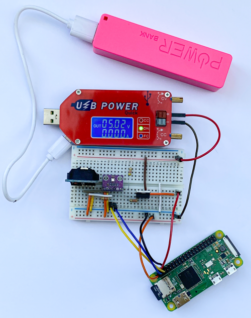
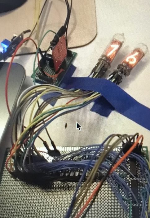
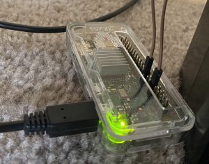
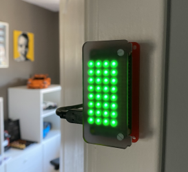
A sleeping Raspberry Pi Zero apparently consuming no current!

You’ll need:

  • DS3231 powered real-time clock module with battery backup: make sure it has a battery holder and an INT/SQW output pin
  • P-channel MOSFET: the IRF9540N works well
  • Three resistors: 2.2 kΩ, 4.7 kΩ, and 220 Ω
  • A device you want to control: this can be a PIC, Arduino, ESP8266, ESP32, or Raspberry Pi. My software is written in Python and works in MicroPython or on Raspberry Pi, but you can find DS3231 driver software for lots of devices
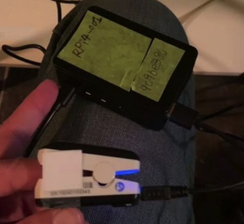
  • Sensor you want to use: we’re using a BME280 to get air temperature, pressure, and humidity
  • Breadboard or prototype board to build up the circuit

We’ll be using a DS3231 real-time clock which is sold in a module, complete with a battery. The DS3231 contains two alarms and can produce a trigger signal to control a power switch. To keep our software simple, we are going to implement an interval timer, but there is nothing to stop you developing software that turns on your hardware on particular days of the week or days in the month. The DS3231 is controlled using I2C, which means it can be used with lots of devices.

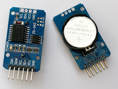
You can pick up one of these modules from lots of suppliers. Make sure that you get one with the SQW connection, as that provides the alarm signal

MOSFET accompli

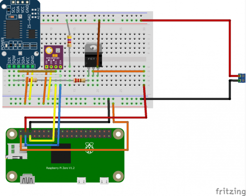
The power to our Raspberry Pi Zero is controlled via a P-channel MOSFET device operating as a switch. The 3.3 V output from Raspberry Pi is used to power the DS3231 and our BME280 sensor. The gate on the MOSFET is connected via a resistor network to the SQW output from the DS3231.

You can think of a MOSFET as a kind of switch. It has a source pin (where we supply power), a drain pin (which is the output the MOSFET controls), and a gate pin. If we change the voltage on the gate pin, this will control whether the MOSFET conducts or not.

We use a P-channel MOSFET to switch the power because the gate voltage must be pulled down to cause the MOSFET to conduct, and that is how P-channel devices function.

MOSFET devices are all about voltage. Specifically, when the voltage difference between the source and the gate pin reaches a particular value, called the threshold voltage, the MOSFET will turn on. The threshold voltage is expressed as a negative value because the voltage on the gate must be lower than the voltage on the source. The MOSFET that we’re using turns on at a threshold voltage of around -3.7 volts and off at a voltage of -1.75 volts.

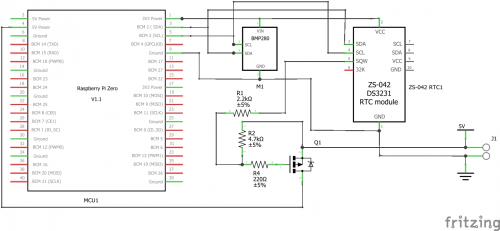
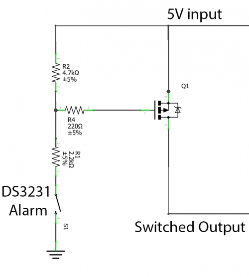
The SQW signal from the DS3231 is controlled by a transistor which is acting as a switch connected to ground inside the DS3231. When the alarm is triggered, this transistor is turned on, connecting the SQW pin to ground. The diagram below shows how this works.

The resistors R1 and R2 are linked to the supply voltage at one end and the SQW pin and the MOSFET gate on the other. When SQW is turned off the voltage on the MOSFET gate is pulled high by the resistors, so the MOSFET turns off. When SQW is turned on, it pulls the voltage on the MOSFET gate down, turning it on.

Unfortunately, current leaking through R1 and R2 to the DN3231 means that we are not going to get zero current consumption when the MOSFET is turned off, but it is much less than 1 milliamp.

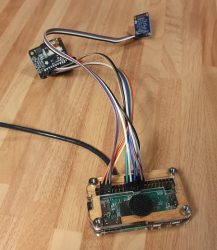
We’re using a BME280 environmental sensor on this device. It is connected via I2C to Raspberry Pi. You don’t need this sensor to implement the power saving
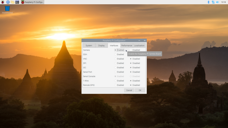
Power control

Now that we have our hardware built, we can get some code running to control the power. The DS3231 is connected to Raspberry Pi using I2C. Before you start, you must enable I2C on your Raspberry Pi using the raspi-config tool. Use sudo raspi-config and select Interfacing Options. Next, you need to make sure that you have all the I2C libraries installed by issuing this command at a Raspberry Pi console:

sudo apt-get install python3-smbus python3-dev i2c-tools

The sequence of operation of our sensor is as follows:

  1. The program does whatever it needs to do. This is the action that you want to perform at regular intervals. That may be to read a sensor and send the data onto the network, or write it to a local SD card or USB memory key. It could be to read something and update an e-ink display. You can use your imagination here.
  2. The program then sets an alarm in the DS3231 at a point in the future, when it wants the power to come back on.
  3. Finally, the program acknowledges the alarm in the DS3231, causing the SQW alarm output to change state and turn off the power.

Clock setting

The program below only uses a fraction of the capabilities of the DS3231 device. It creates an interval timer that can time hours, minutes, and seconds. Each time the program runs, the clock is set to zero, and the alarm is configured to trigger when the target time is reached.

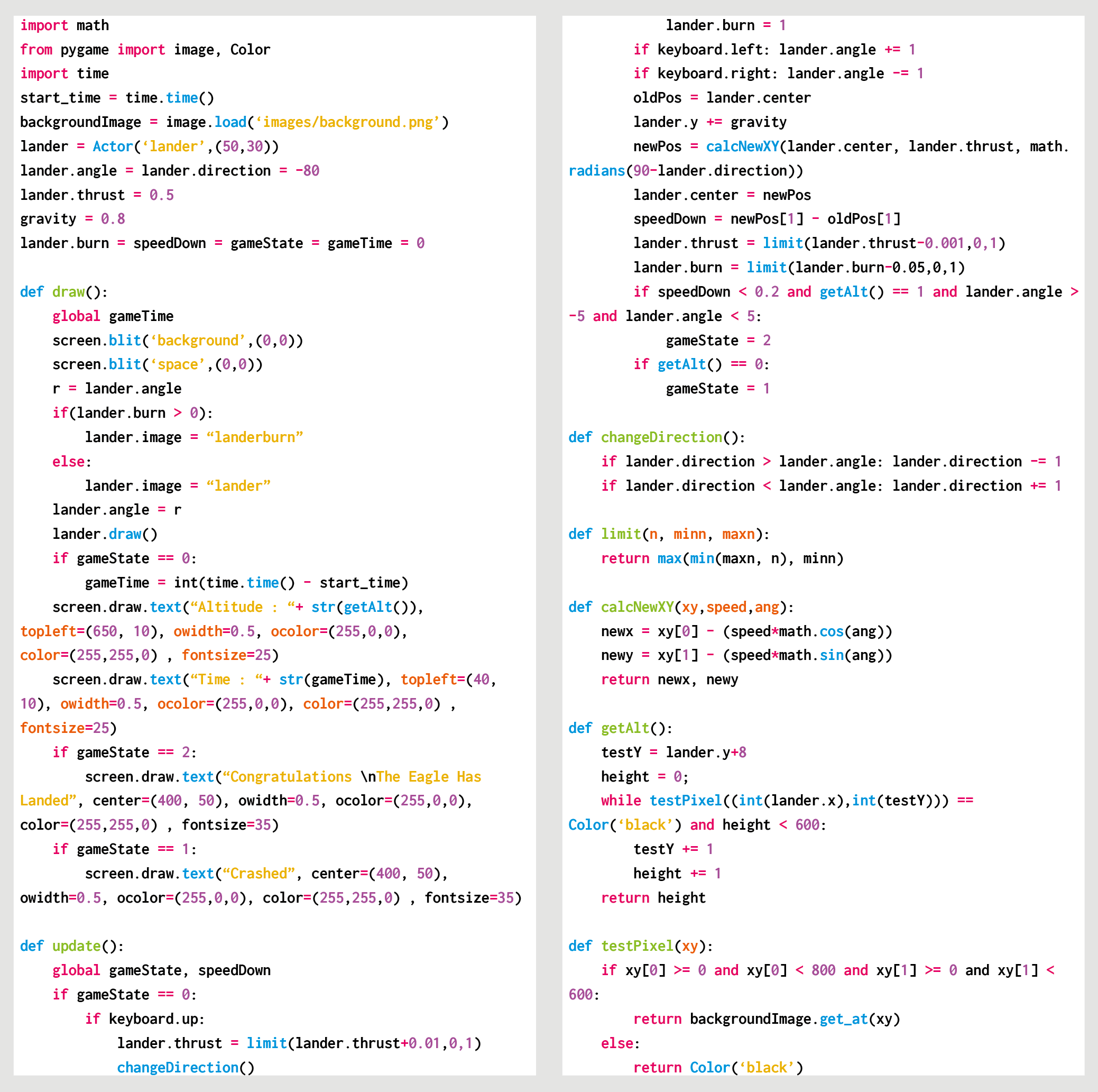
Put the program into a file called SensorAction.py on your Raspberry Pi, and put the code that you want to run into the section indicated.

import smbus

bus = smbus.SMBus(1)

DS3231 = 0x68

SECONDS_REG = 0x00
ALARM1_SECONDS_REG = 0x07

CONTROL_REG = 0x0E
STATUS_REG = 0x0F

def int_to_bcd(x):
    return int(str(x)[-2:], 0x10)

def write_time_to_clock(pos, hours, minutes, seconds):
    bus.write_byte_data(DS3231, pos, int_to_bcd(seconds))
    bus.write_byte_data(DS3231, pos + 1, int_to_bcd(minutes))
    bus.write_byte_data(DS3231, pos +2, int_to_bcd(hours))

def set_alarm1_mask_bits(bits):
    pos = ALARM1_SECONDS_REG
    for bit in reversed(bits):
        reg = bus.read_byte_data(DS3231, pos)
        if bit:
            reg = reg | 0x80
        else:
            reg = reg & 0x7F
        bus.write_byte_data(DS3231, pos, reg)
        pos = pos + 1

def enable_alarm1():
    reg = bus.read_byte_data(DS3231, CONTROL_REG)
    bus.write_byte_data(DS3231, CONTROL_REG, reg | 0x05)

def clear_alarm1_flag():
    reg = bus.read_byte_data(DS3231, STATUS_REG)
    bus.write_byte_data(DS3231, STATUS_REG, reg & 0xFE)

def check_alarm1_triggered():
    return bus.read_byte_data(DS3231, STATUS_REG) & 0x01 != 0

def set_timer(hours, minutes, seconds):
    # zero the clock
    write_time_to_clock(SECONDS_REG, 0, 0, 0)
    # set the alarm
    write_time_to_clock(ALARM1_SECONDS_REG, hours, minutes, seconds)
    # set the alarm to match hours minutes and seconds
    # need to set some flags
    set_alarm1_mask_bits((True, False, False, False))
    enable_alarm1()
    clear_alarm1_flag()

#
# Your sensor behaviour goes here
#
set_timer(1,30,0)

The set_timer function is called to set the timer and clear the alarm flag. This resets the alarm signal and powers off the sensor. The example above will cause the sensor to shut down for 1 hour 30 minutes.

You can use any other microcontroller that implements I2C

Power down

The SensorAction program turns off your Raspberry Pi without shutting it down properly, which is something your mother probably told you never to do. The good news is that in extensive testing, we’ve not experienced any problems with this. However, if you want to make your Raspberry Pi totally safe in this situation, you should make its file system ‘read-only’, which means that it never changes during operation and therefore can’t be damaged by untimely power cuts. There are some good instructions from Adafruit here: hsmag.cc/UPgJSZ.

Note: making the operating system file store read-only does not prevent you creating a data logging application, but you would have to log the data to an external USB key or SD card and then dismount the storage device before killing the power.

If you are using a different device, such as an ESP8266 or an Arduino, you don’t need to worry about this as the software in them is inherently read-only.

The SQW output from the DS3231 will pull the gate of the MOSFET low to turn on the power to Raspberry Pi

Always running

To get the program to run when the Raspberry Pi boots, use the Nano editor to add a line at the end of the rc.local file that runs your program.

sudo nano /etc/rc.local

Use the line above at the command prompt to start editing the rc.local file and add the following line at the end of the file:

python3 /home/pi/SensorAction.py &

This statement runs Python 3, opens the SensorAction.py file, and runs it. Don’t forget the ampersand (&) at the end of the command: this starts your program as a separate process, allowing the boot to complete. Now, when Raspberry Pi boots up, it will run your program and then shut itself down. You can find a full sample application on the GitHub pages for this project (hsmag.cc/Yx7q6t). It logs air temperature, pressure, and humidity to an MQTT endpoint at regular intervals. Now, go and start tracking that marrow temperature!

Issue 30 of HackSpace magazine is out now

The latest issue of HackSpace magazine is on sale now, and you can get your copy from the Raspberry Pi Press online store. You can also download it for free to check it out first.

UK readers can take advantage of our special subscriptions offer at the moment.

3 issues for £10 & get a free book worth £10…

If you’re in the UK, get your first three issues of HackSpace magazine, The MagPi, Custom PC, or Digital SLR Photography delivered to your door for £10, and choose a free book (itself worth £10) on top!

The post Build low-power, clock-controlled devices appeared first on Raspberry Pi.


Source: Raspberry Pi – Build low-power, clock-controlled devices

University of Toronto supports COVID-19 patient monitoring with Raspberry Pi

A member of the Raspberry Pi community in Ontario, Canada spotted this story from the University of Toronto on CBC News. Engineers have created a device that enables healthcare workers to monitor COVID-19 patients continuously without the need to enter their hospital rooms.

Continuous, remote monitoring

Up-to-date information can be checked from any nursing station computer or smartphone. This advance could prove invaluable in conserving Personal Protective Equipment (PPE) supplies, which staff have to don for each hospital room visit. It also allows for the constant monitoring of patients at a time when hospital workers are extremely stretched.

Mount Sinai Hospital approached the University of Toronto’s engineering department to ask for their help in finding a way to monitor vital signs both continuously and remotely. A team of three PhD students, led by Professor Willy Wong, came up with the solution in just three days.

Communicating finger-clip monitor measurements

The simple concept involves connecting a Raspberry Pi 4 to standard finger-clip monitors, already in use across the hospital to monitor the respiratory status of COVID-19 patients. The finger clips detect what light is absorbed by the blood in a patient’s finger. Blood absorbs different colours of light to different degrees depending on how well oxygenated it is, so these measurements tell medical staff whether patients might be having difficulty with breathing.

The Raspberry Pi communicates this information over a wireless network to a server that Wong’s team deployed, allowing the nurses’ station computers or doctors’ smartphones to access data on how their patients are doing. This relieves staff of the need enter patients’ rooms to check the data output on bedside monitors.

Photo by Professor Wong, sourced from CBC News

A successful prototype

Feedback has been unanimously positive since several prototypes were deployed in a trial at Mount Sinai. And a local retirement home has been in touch to ask about using the invention to help care for their residents. Professor Wong says solutions like this one are a “no-brainer” when trying to monitor large groups of people as healthcare workers battle COVID-19. “This was a quintessentially electrical and computer engineering problem,” he explains.

Professor Wong’s team included PhD candidates Bill Shi, Yan Li, and Brian Wang.

The University of Toronto is also home to engineers who are currently developing an automated, more sensitive and rapid test for COVID-19. You can read more about their project, which is based on quantum dots – nano-scale particles that bind to different components of the virus’s genetic material and glow brightly in different colours when struck by light. This gives multiple data points per patient sample and provides increased confidence in test results.

The post University of Toronto supports COVID-19 patient monitoring with Raspberry Pi appeared first on Raspberry Pi.


Source: Raspberry Pi – University of Toronto supports COVID-19 patient monitoring with Raspberry Pi

Code a homage to Lunar Lander | Wireframe #37

Shoot for the moon in our Python version of the Atari hit, Lunar Lander. Mark Vanstone has the code.

Atari’s cabinet featured a thrust control, two buttons for rotating, and an abort button in case it all went horribly wrong.

Lunar Lander

First released in 1979 by Atari, Lunar Lander was based on a concept created a decade earlier. The original 1969 game (actually called Lunar) was a text-based affair that involved controlling a landing module’s thrust to guide it safely down to the lunar surface; a later iteration, Moonlander, created a more visual iteration of the same idea on the DEC VT50 graphics terminal.

Given that it appeared at the height of the late-seventies arcade boom, though, it was Atari’s coin-op that became the most recognisable version of Lunar Lander, arriving just after the tenth anniversary of the Apollo 11 moon landing. Again, the aim of the game was to use rotation and thrust controls to guide your craft, and gently set it down on a suitably flat platform. The game required efficient control of the lander, and extra points were awarded for parking successfully on more challenging areas of the landscape.

The arcade cabinet was originally going to feature a normal joystick, but this was changed to a double stalked up-down lever providing variable levels of thrust. The player had to land the craft against the clock with a finite amount of fuel with the Altitude, Horizontal Speed, and Vertical Speed readouts at the top of the screen as a guide. Four levels of difficulty were built into the game, with adjustments to landing controls and landing areas.

Our homage to the classic Lunar Lander. Can you land without causing millions of dollars’ worth of damage?

Making the game

To write a game like Lunar Lander with Pygame Zero, we can replace the vector graphics with a nice pre-drawn static background and use that as a collision detection mechanism and altitude meter. If our background is just black where the Lander can fly and a different colour anywhere the landscape is, then we can test pixels using the Pygame function image.get_at() to see if the lander has landed. We can also test a line of pixels from the Lander down the Y-axis until we hit the landscape, which will give us the lander’s altitude.

The rotation controls of the lander are quite simple, as we can capture the left and right arrow keys and increase or decrease the rotation of the lander; however, when thrust is applied (by pressing the up arrow) things get a little more complicated. We need to remember which direction the thrust came from so that the craft will continue to move in that direction even if it is rotated, so we have a direction property attached to our lander object. A little gravity is applied to the position of the lander, and then we just need a little bit of trigonometry to work out the movement of the lander based on its speed and direction of travel.

To judge if the lander has been landed safely or rammed into the lunar surface, we look at the downward speed and angle of the craft as it reaches an altitude of 1. If the speed is sufficiently slow and the angle is near vertical, then we trigger the landed message, and the game ends. If the lander reaches zero altitude without these conditions met, then we register a crash. Other elements that can be added to this sample are things like a limited fuel gauge and variable difficulty levels. You might even try adding the sounds of the rocket booster noise featured on the original arcade game.

Engage

The direction of thrust could be done in several ways. In this case, we’ve kept it simple, with one directional value which gradually moves in a new direction when an alternative thrust is applied. You may want to try making an X- and Y-axis direction calculation for thrust so that values are a combination of the two dimensions. You could also add joystick control to provide variable thrust input.

Here’s Mark’s code snippet, which creates a simple shooting game in Python. To get it working on your system, you’ll need to install Pygame Zero. And to download the full code and assets, go here.

Get your copy of Wireframe issue 36

You can read more features like this one in Wireframe issue 37, available directly from Raspberry Pi Press — we deliver worldwide.

And if you’d like a handy digital version of the magazine, you can also download issue 37 for free in PDF format.

Make sure to follow Wireframe on Twitter and Facebook for updates and exclusive offers and giveaways. Subscribe on the Wireframe website to save up to 49% compared to newsstand pricing!

The post Code a homage to Lunar Lander | Wireframe #37 appeared first on Raspberry Pi.


Source: Raspberry Pi – Code a homage to Lunar Lander | Wireframe #37

Track your cat’s activity with a homemade speedometer

Firstly, hamster wheels for cats are (still) a thing. Secondly, Bengal cats run far. And Shawn Nunley on reddit is the latest to hit on this solution for kitty exercise and bonus cat stats.

Here is the wheel itself. That part was shop-bought. (Apparently it’s a ZiggyDoo Ferris Cat Wheel.)

Smol kitty in big wheel

Shawn has created a speedometer that tracks distance and speed. Every time a magnet mounted on the wheel passes a fixed sensor, a Raspberry Pi Zero writes to a log file so he can see how far and fast his felines have travelled. The wheel has six sensors, which each record 2.095 ft of travel. This project revealed the cats do about 4-6 miles per night on their wheel, and they reach speeds of 14 miles an hour.

Here’s your shopping list:

The tiny white box sticking out at the base of the wheel is the sensor

Shawn soldered a 40-pin header to his Raspberry Pi Zero and used jumper wires to connect to the sensor. He mounted the sensor to the cat wheel using hot glue and a pill box cut in half, which provided the perfect offset so it could accurately detect the magnets passing by. The code is written in Python.

Upcoming improvements include adding RFID so the wheel can distinguish between the cats in this two-kitty household.

Shawn also plans to calculate how much energy the Bengals are expending, and he’ll soon be connecting the Raspberry Pi to their Google Cloud Platform account so you can all keep up with the cats’ stats.

The stats are currently available only locally

And, get this – this was Shawn’s first ever time doing anything with Raspberry Pi or Python. OK, so as an ex-programmer he had a bit of a head start, but he assures us he hasn’t touched the stuff since the 1990s. He explains: “I was totally shocked at how easy it was once I figured out how to get the Raspberry Pi to read a sensor.” Start to finish, the project took him just one week.

The post Track your cat’s activity with a homemade speedometer appeared first on Raspberry Pi.


Source: Raspberry Pi – Track your cat’s activity with a homemade speedometer

Create your own home office work status light with Raspberry Pi

If you’re working from home and you have children, you’re probably finding it all pretty demanding at the moment. Spreadsheets and multiple tabs and concentrating aren’t nearly so manageable without the dedicated workspace you have at the office and with, instead, small people vying relentlessly for your attention.

And that’s not to mention the horror that is arranging video conference calls and home life around one another. There’s always the danger that a housemate (young offspring or otherwise) might embarrassingly crash your formal party like what happened to Professor Robert Kelly live on BBC News. (See above. Still funny!)

Well, Belgian maker Elio Struyf has created a homemade solution to mitigate against such unsolicited workspace interferences: he built a status light that integrates with Microsoft Teams so that his kids know when he’s on a call and they should stay away from his home office.

DIY busy light created with Raspberry Pi and Pimoroni Unicorn pHAT

The light listens to to Elio’s Microsoft Teams status and accordingly displays the colour red if he’s busy chatting online, yellow if his status is set to ‘Away’, or green if he’s free for his kids to wander in and say “Hi”.

Here’s what you need to build your own:

The Pimoroni Unicorn pHAT has an 8×4 grid of RGB LEDs that Elio set to show a single colour (though you can tell them to display different colours). His Raspberry Pi runs DietPi, which is a lightweight Debian distro. On top of this, running Homebridge makes it compatible with Apple’s HomeKit libraries, which is how Elio was able to connect the build with Microsoft Teams on his MacBook.

Elio’s original blog comprehensively walks you through the setup process, so you too can try to manage your home working plus domestic duties. All you need is to get your five-year-old to buy into your new traffic-light system, and with that we wish you all the luck in the world.

And give Elio a follow on Twitter. Fella has mad taste in T-shirts.

The post Create your own home office work status light with Raspberry Pi appeared first on Raspberry Pi.


Source: Raspberry Pi – Create your own home office work status light with Raspberry Pi

Resurrecting a vintage microwave sensor with Raspberry Pi

Here’s one of those lovely “old tech new spec” projects, courtesy of hackster.io pro Martin Mander.

After finding a vintage Apollo microwave detector at a car boot sale, and realising the display hole in the top was roughly the same size as a small Adafruit screen, he saw the potential to breath new life into its tired exterior. And resurrected it as a thermal camera!

Right up top – the finished product!

Martin assumes it would have been used to test microwave levels in some kind of industrial setting, given microwave ovens were a rarity when it was produced.

Old components stripped and ready for a refit

Anyhow, a fair bit of the original case needed to be hacked at or sawn off to make sure all the new components could fit inside.  A Raspberry Pi Zero provides the brains of the piece. Martin chose this because he wanted to run the scipy python module to perform bicubic interpolation on the captured data, making the captured images look bigger and better. The thermal sensor is an Adafruit AMG8833IR Thermal Camera Breakout, which uses an 8×8 array of sensors to create the heat image.

The tiny but readable display screen

The results are displayed in real time on a bright 1.3″ TFT display. Power comes from a cylindrical USB battery pack concealed in the hand grip, which is recharged by opening up the nose cone and plugging in a USB lead. Just three Python scripts control the menu logic, sensor, and Adafruit.io integration, with the display handled by PyGame.

It gets better: with the click of a button, a snapshot of whatever the thermal camera is looking at is taken and then uploaded to an Adafruit dashboard for you to look at or share later.

Sensor and screen wired up

Martin’s original post is incredibly detailed, walking you through the teardown of the original piece, the wiring, how to tweak all the code and, of course, how he went about giving it that fabulous BB-8 orange-and-white makeover. He recorded the entire process in this 24-minute opus:

Apollo Pi Thermal Camera

This vintage Apollo microwave detector now has a shiny new purpose as a thermal camera, powered by a Raspberry Pi Zero with an Adafruit thermal camera sensor…

But what can you actually do with it? Martin’s suggestions range from checking your beer is cold enough before opening it, to testing your washing machine temperature mid-cycle. If you watch his video, you’ll see he’s also partial to monitoring cat tummy temperatures. His kid doesn’t like having his forehead Apollo Pi’d though.

Check out more of Martin’s projects on hackster.io.

The post Resurrecting a vintage microwave sensor with Raspberry Pi appeared first on Raspberry Pi.


Source: Raspberry Pi – Resurrecting a vintage microwave sensor with Raspberry Pi

Special offer for magazine readers

You don’t need me to tell you about the unprecedented situation that the world is facing at the moment. We’re all in the same boat, so I won’t say anything about it other than I hope you stay safe and take care of yourself and your loved ones.

The other thing I will say is that every year, Raspberry Pi Press produces thousands of pages of exciting, entertaining, and often educational content for lovers of computing, technology, games, and photography.

In times of difficulty, it’s not uncommon for people to find solace in their hobbies. The problem you’ll find yourself with is that it’s almost impossible to buy a magazine at the moment, at least in the UK: most of the shops that sell them are closed (and even most of their online stores are too).

We’re a proactive bunch, so we’ve done something about that:


From today, you can subscribe to The MagPi, HackSpace magazine, Custom PC, or Digital SLR Photography at a cost of three issues for £10 in the UK – and we’re giving you a little extra too.

We like to think we produce some of the best-quality magazines on the market today (and you only have to ask our mums if you want a second opinion). In fact, we’d go as far as to say our magazines are exactly the right mix of words and pictures for making the most of all the extra home-time you and your loved ones are having.

Take your pick for three issues at £10 and get a free book worth £10!

If you take us up on this offer, we’ll send the magazines direct to your door in the UK, with free postage. And we’re also adding a gift to thank you for signing up: on top of your magazines, you’ll get to choose a book that’s worth £10 in itself.

In taking up this offer, you’ll get some terrific reading material, and we’ll deliver it all straight to you — no waiting around. You’ll also be actively supporting our print magazines and the charitable work of the Raspberry Pi Foundation.

I hope that among our magazines, you’ll find something that’s of interest to you or, even better yet, something that sparks a new interest. Enjoy your reading!

The post Special offer for magazine readers appeared first on Raspberry Pi.


Source: Raspberry Pi – Special offer for magazine readers