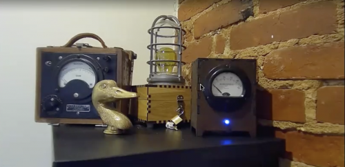
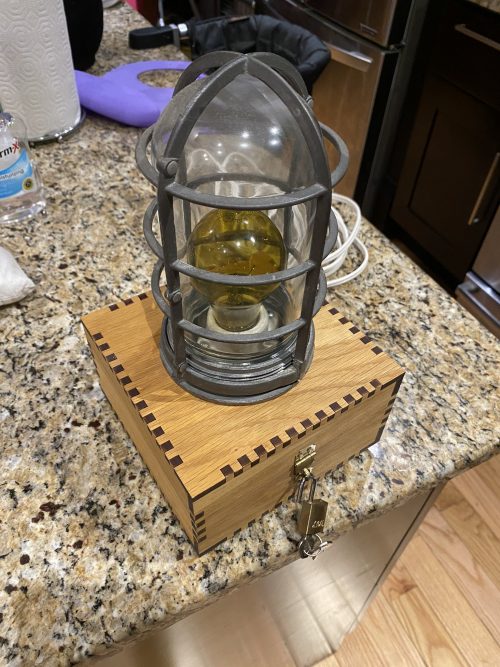
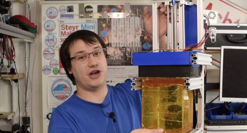
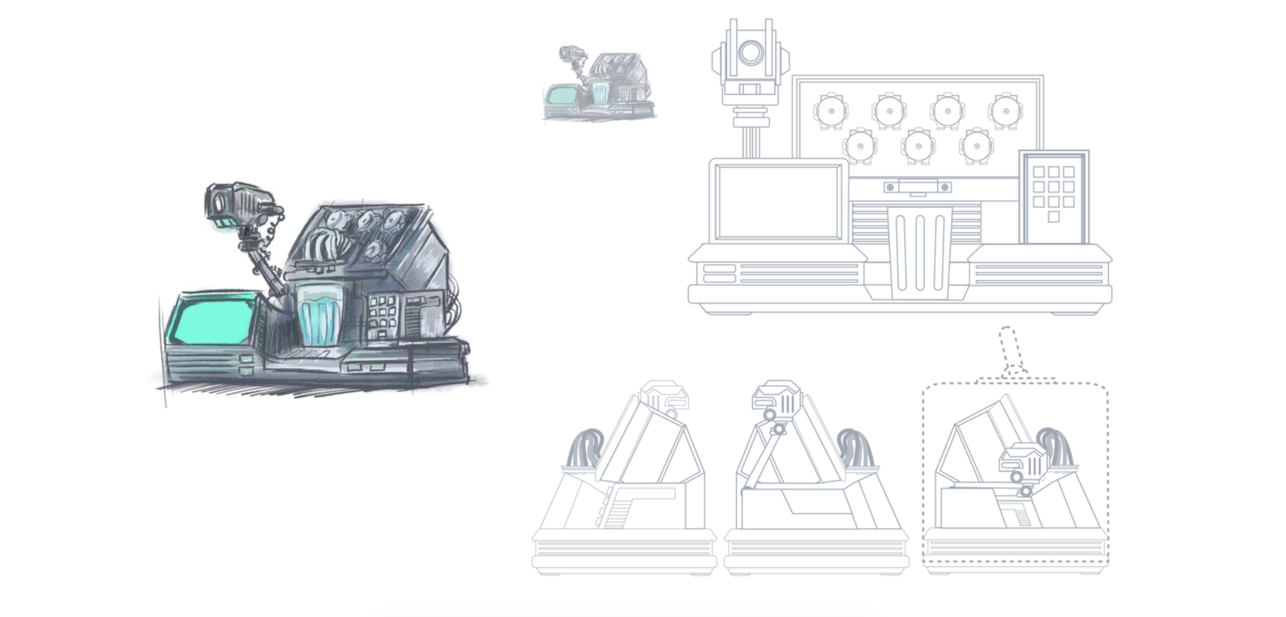
Three things we like: Blade Runner, robots, and cocktails. That’s why we LOVE Donald Bell‘s Raspberry Pi–packed ‘VK-01 Off-World Bartender‘ cocktail making machine.
This machine was due to be Donald’s entry into the Cocktail Robotics Grand Challenge, an annual event in San Francisco. By the time the event was cancelled, he was too deep into his awesome build to give up, so he decided to share it with the Instructables community instead.
Donald wanted users to get as much interaction and feedback as possible, rather than simply pressing a button and receiving a random drink. So with this machine, the interaction comes in four ways: instructions provided on the screen, using a key card to bypass security, placing and removing a cup on the tray, and entering an order number on the keypad.
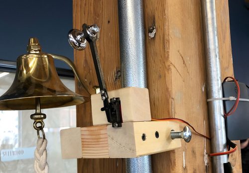
In addition to that, feedback is provided by way of lighting changes, music, video dialogue, pump motors whirring, and even the clicks of relays at each stage of the cocktail making process.
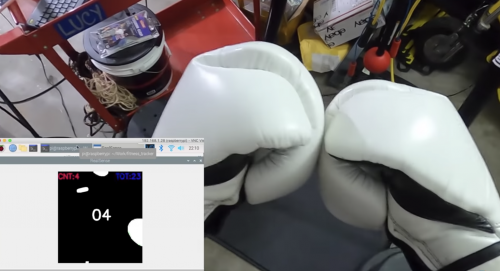
Ordering on the keypad
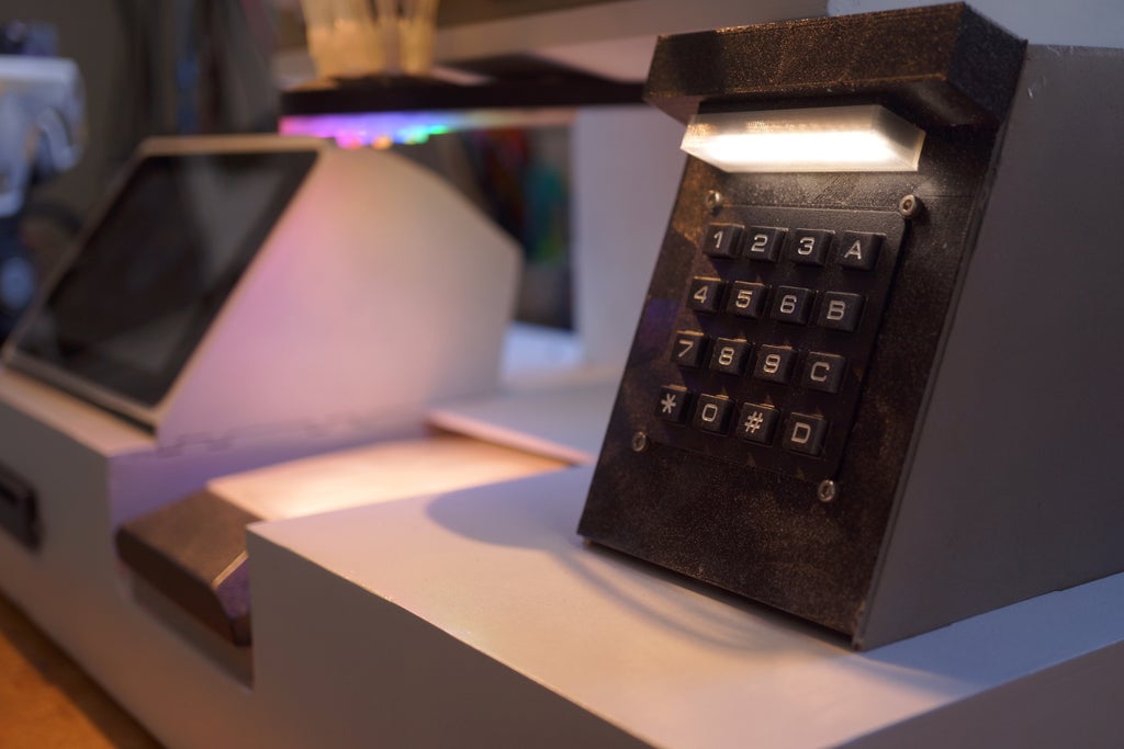
The keypad allows people to punch in a number to trigger their order, like on a vending machine. The drink order is sent to the Hello Drinkbot software running on the Raspberry Pi 3B that controls the pumps.
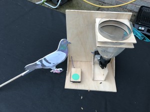
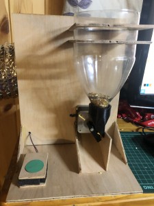
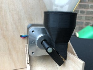
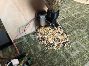
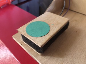
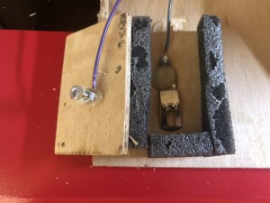
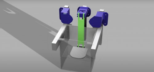
Getting your cup filled
In order for the machine to be able to tell when a vessel is placed under the dispenser spout, and when it’s removed, Donald built in a switch under a 3D-printed tray. Provided the vessel has at least one ice cube in it, even the lightest plastic up is heavy enough to trigger the switch.
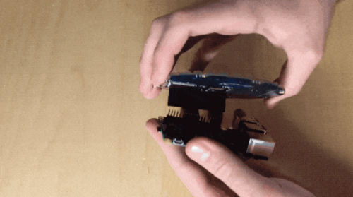
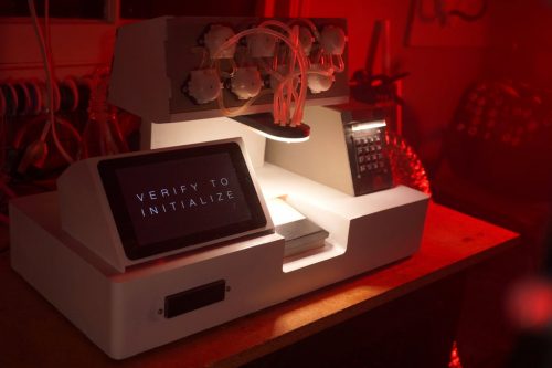
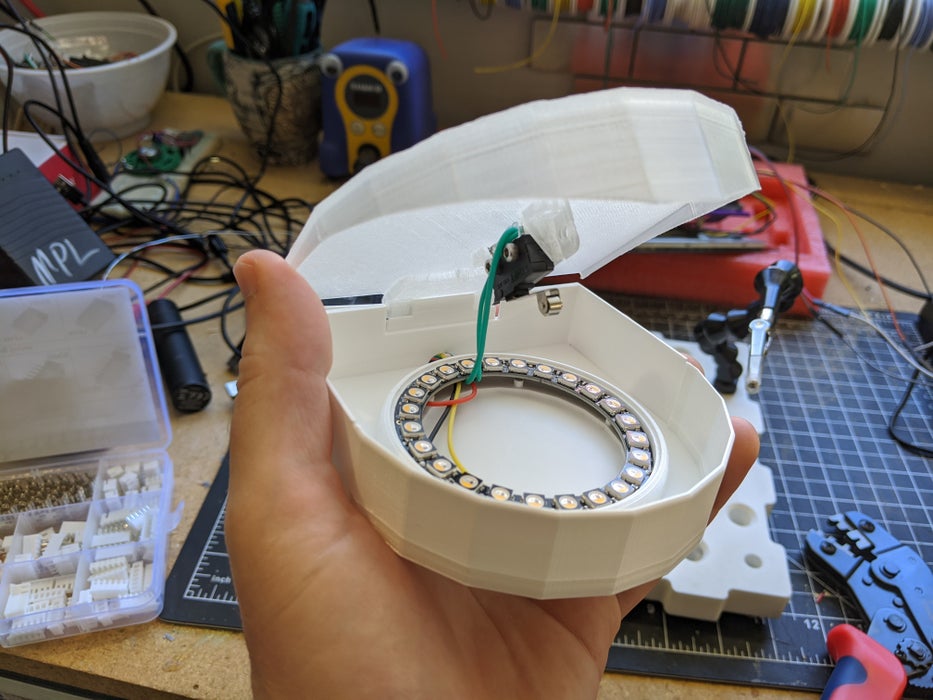
The RFID card reader
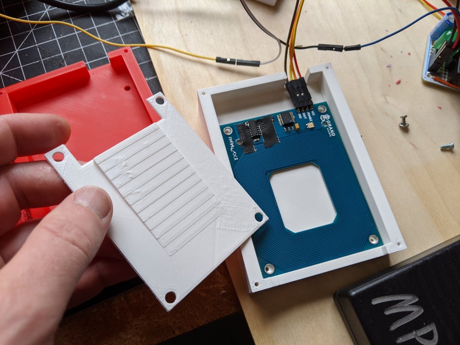
Cocktail machine customers are asked to scan a special ID card to start. To make this work, Donald adapted a sample script that blinks the card reader’s internal LED when any RFID card is detected.
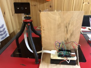
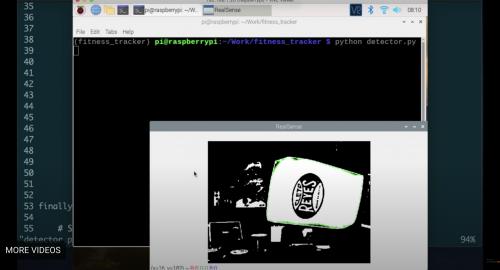
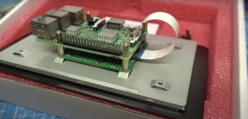
Interactive video screen
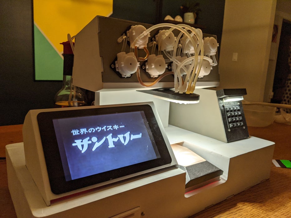
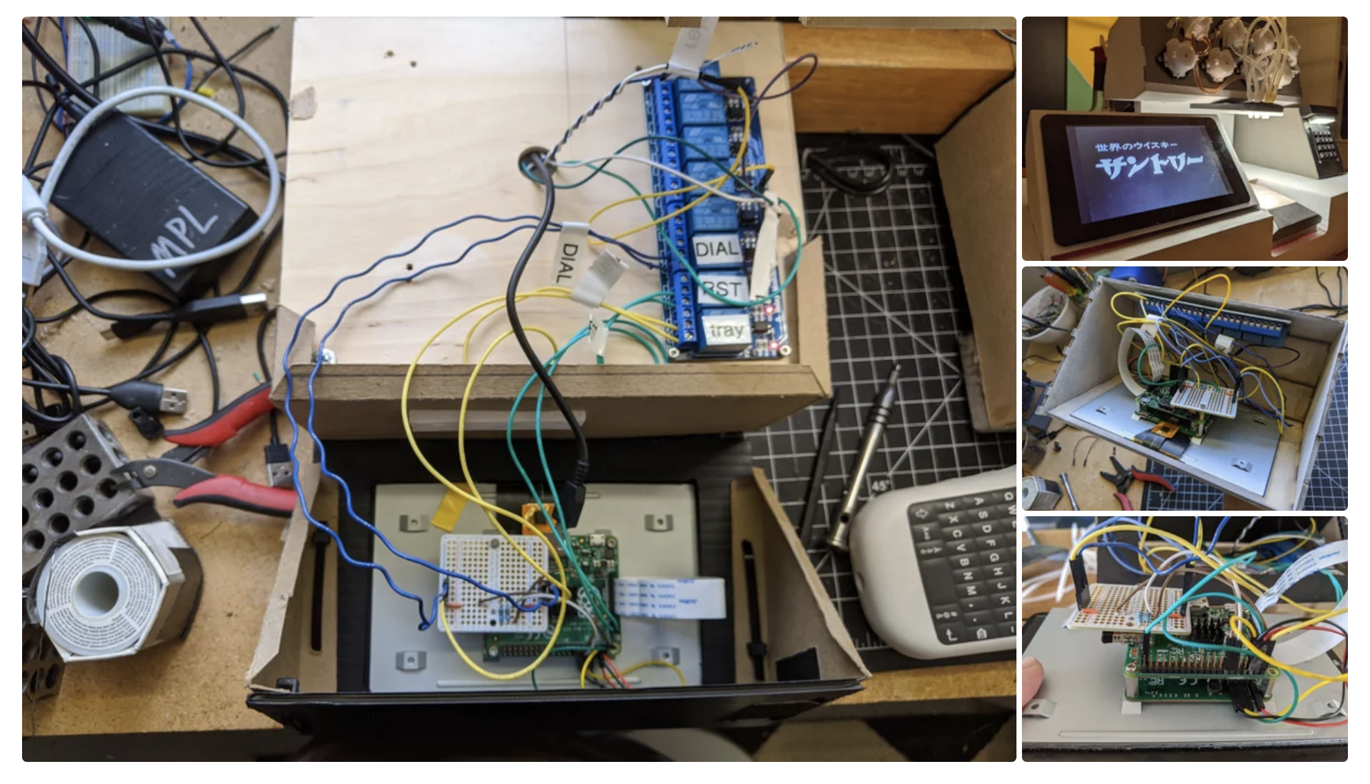
This bit is made possible by MP4Museum, a “bare-bones” kiosk video player software that the second Raspberry Pi inside the machine runs on boot. By connecting a switch to the Raspberry Pi’s GPIO, Donald enabled customers to advance through the videos one by one. And yes, that’s an official Raspberry Pi Touch Display.
The Hello Drinkbot ‘bartender’
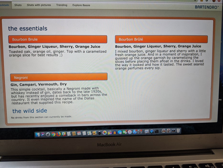
Donald used the Python-based Hello Drinkbot software as the brains of the machine. With it, you can configure which liquors or juices are connected to which pumps, and send instructions on exactly how much to pour of each ingredient. Everything is configured via a web interface.
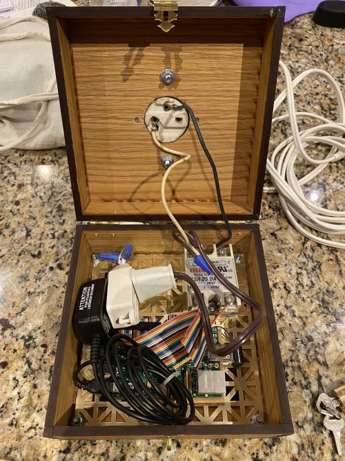
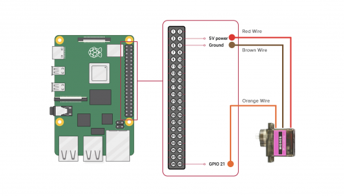
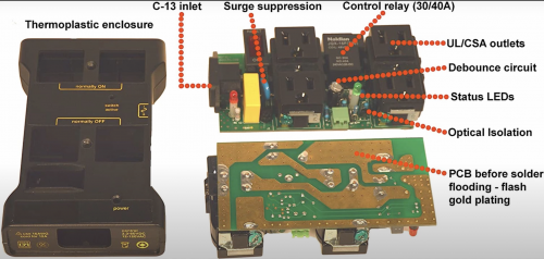
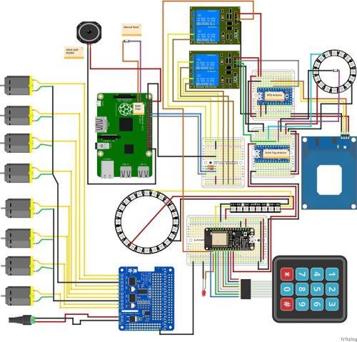
Via a bank of relays, microcontrollers connect all the signals from the Touch Display, keypad, RFID card reader, and switch under the spout.
Supplies
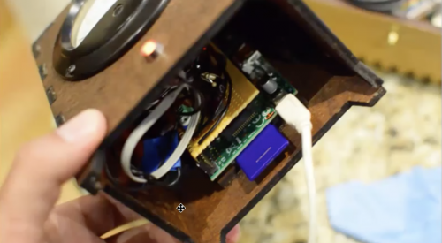
Donald shared an exhaustive kit list on his original post, but basically, what you’re looking at is…
- Raspberry Pi 3B (the one running the Hello Drinkbot software)
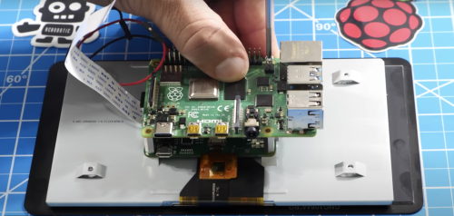
- Raspberry Pi A+ (the one behind the touch screen)
- Raspberry Pi 7-inch touch screen
- Parallax RFID Reader
- Adafruit Feather Huzzah with ESP8266
- Adafruit ItsyBitsy 32u4 – 5V 16MHz (x2)
- 4-channel DC 5V Relay Module
- Zippy-style Momentary micro switches
- Adafruit DC & Stepper Motor HAT for Raspberry Pi
And finally, check out the Raspberry Pi–based Hello Drinkbot project by Rich Gibson, which inspired Donald’s build.
The post Raspberry Pi Off-World Bartender appeared first on Raspberry Pi.
Source: Raspberry Pi – Raspberry Pi Off-World Bartender