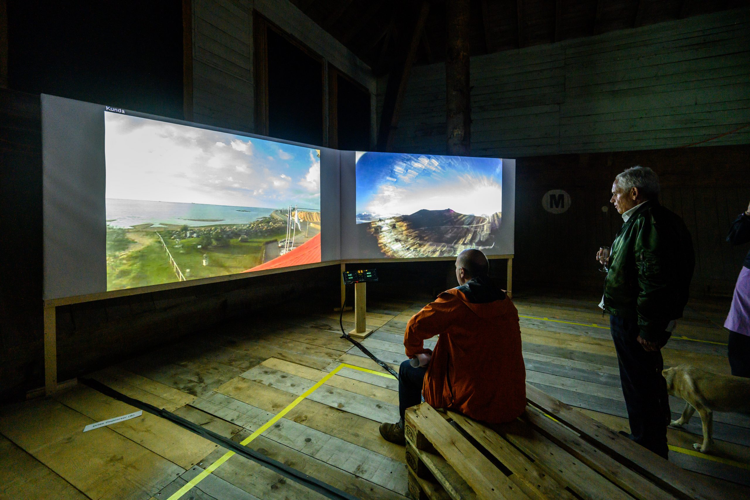
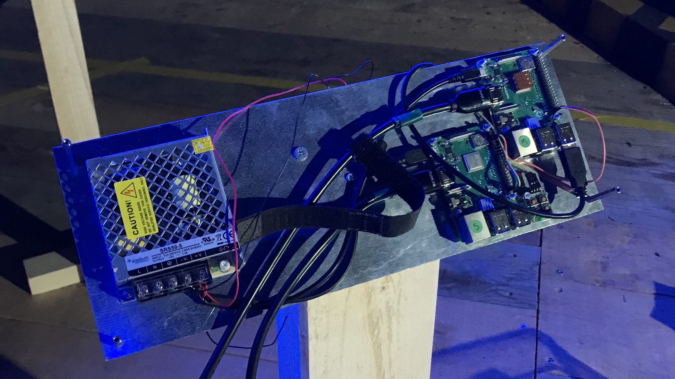
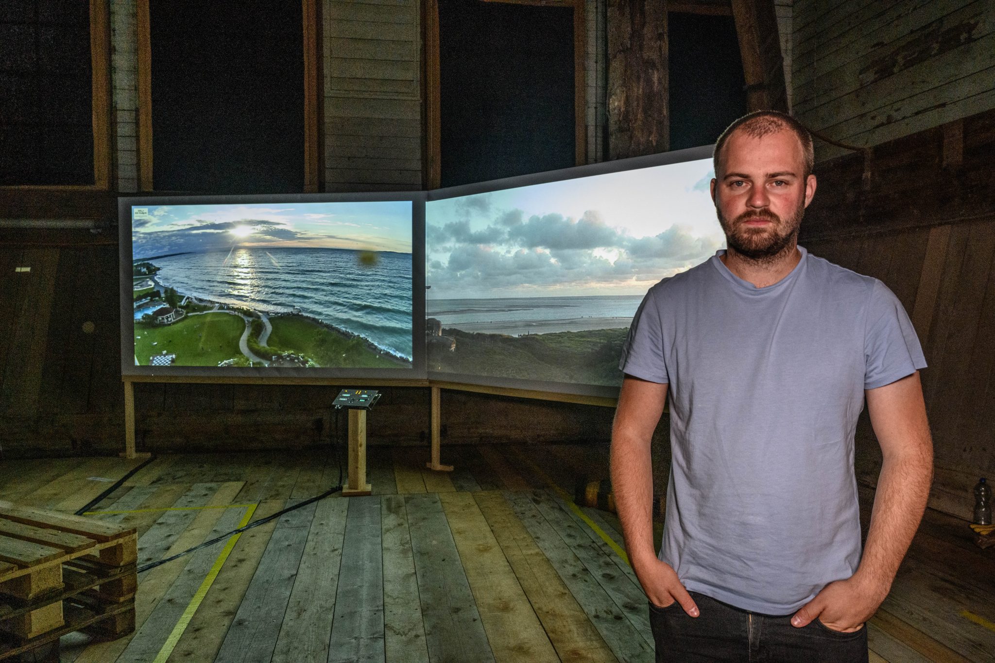
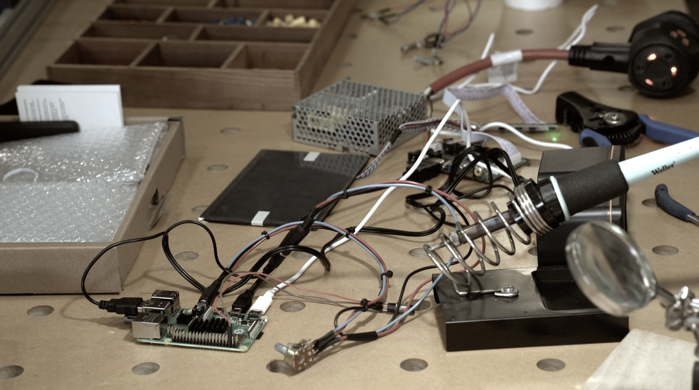
The arresting visuals are beamed to viewers using two Raspberry Pi 3B+ computers and an Arduino Nano Every that stream internet protocol (IP) cameras with the use of command line media player OMXPlayer.
Dual Raspberry Pi power
The two Raspberry Pis communicate with each other using the MQTT protocol — a standard messaging protocol for the Internet of Things (IoT) that’s ideal for connecting remote devices with a small code footprint and minimal network bandwidth.
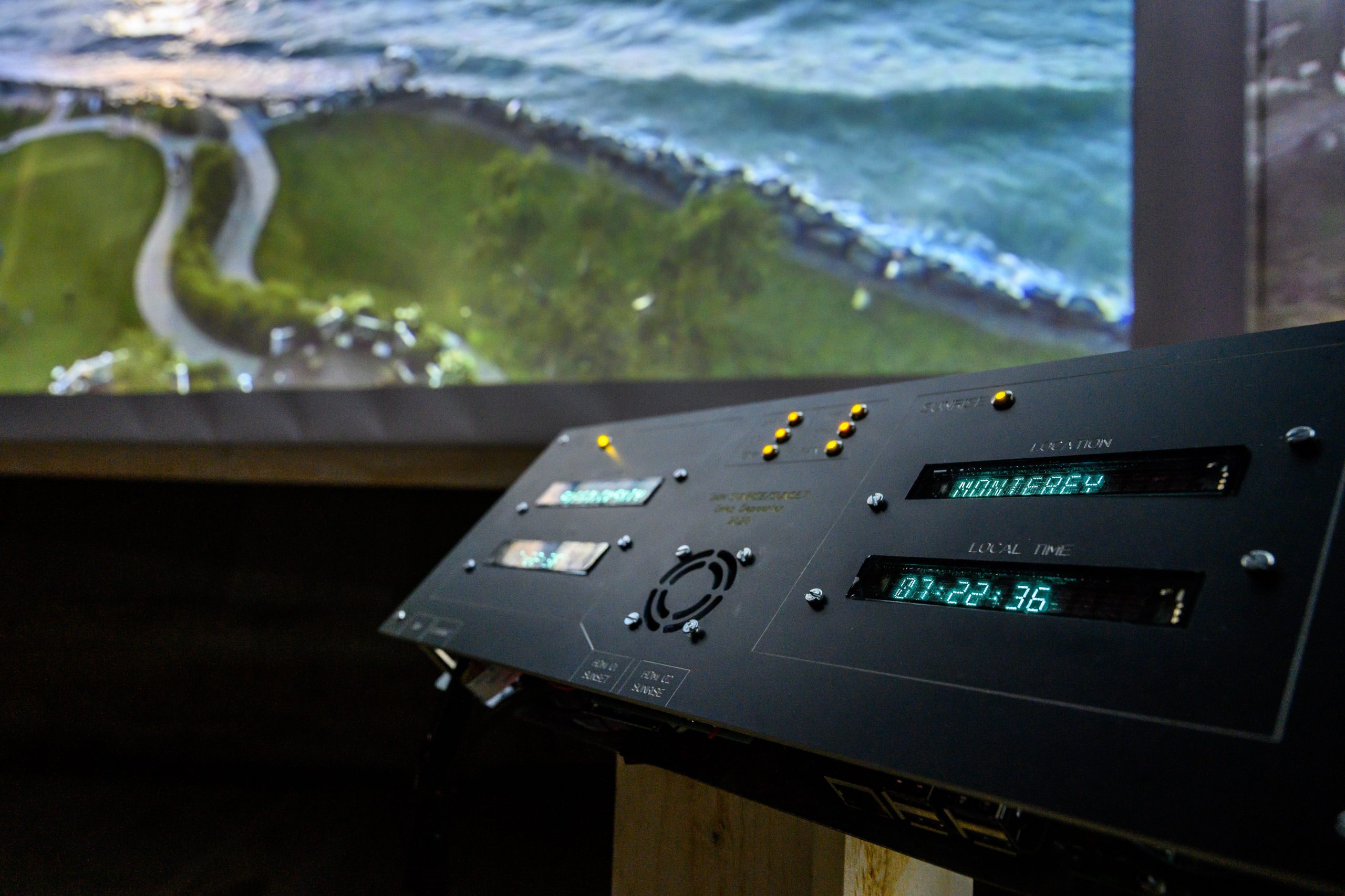
One of the Raspberry Pis checks at which location in the world a sunrise or sunset is happening and streams the closest CCTV camera.
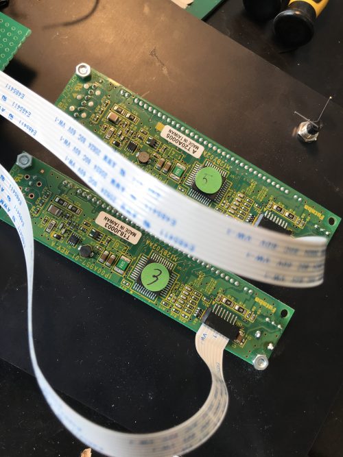
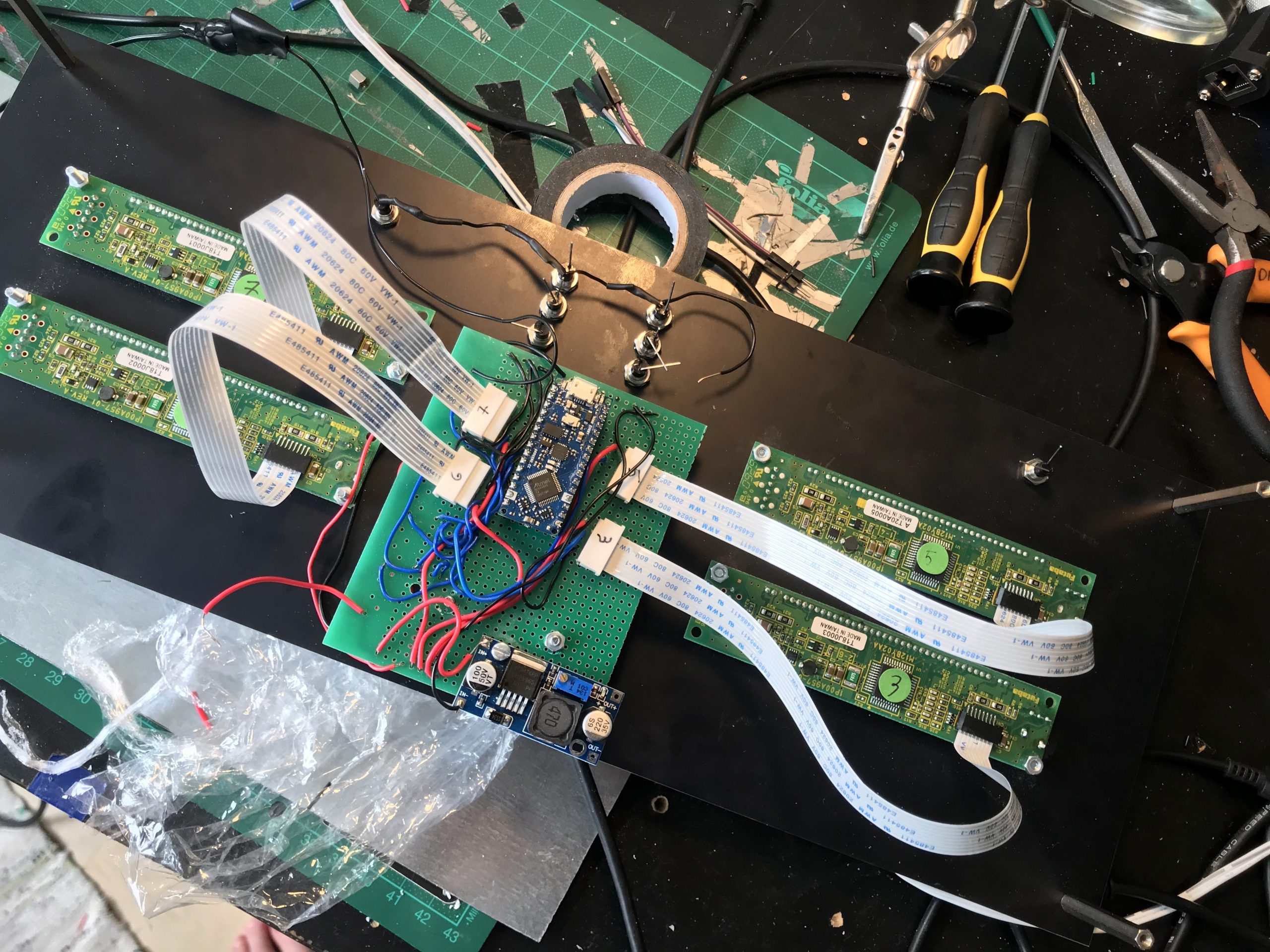
The insides of the sleek display screen…
Beam me out, Scotty
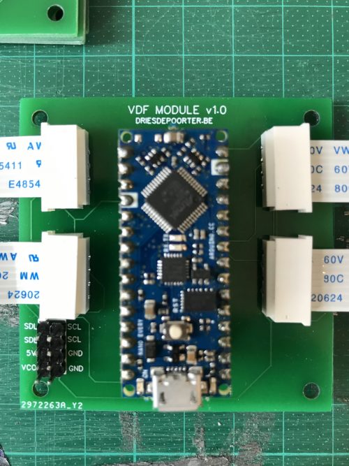
The big screens are connected with the I2C protocol to the Arduino, and the Arduino is connected serial with the second Raspberry Pi. Dries also made a custom printed circuit board (PCB) so the build looks cleaner.
All that hardware is powered by an industrial power supply, just because Dries liked the style of it.
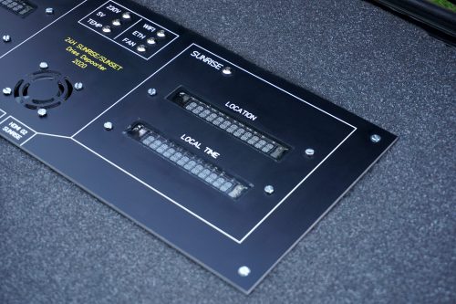
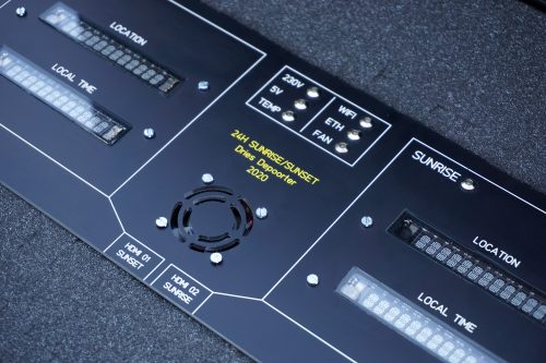
…and the outside
Software
Everything is written in Python 3, and Dries harnessed the Python 3 libraries BeautifulSoup, Sun, Geopy, and Pytz to calculate sunrise and sunset times at specific locations. Google Firebase databases in the cloud help with admin by way of saving timestamps and the IP addresses of the cameras.
Do you know young people who dream of sending something to space? You can help them make that dream a reality!
We’re calling on educators, club leaders, and parents to inspire young people to develop their digital skills by participating in this year’s European Astro Pi Challenge.
The European Astro Pi Challenge, which we run in collaboration with the European Space Agency, gives young people in 26 countries* the opportunity to write their own computer programs and run them on two special Raspberry Pi units — called Astro Pis! — on board the International Space Station (ISS).
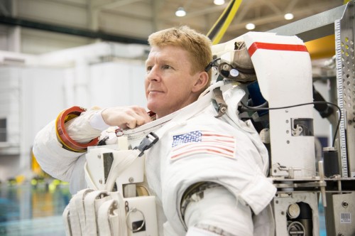
This year’s Astro Pi ambassador is ESA astronaut Thomas Pesquet. Thomas will accompany our Astro Pis on the ISS and oversee young people’s programs while they run.
And the young people need your support to take part in the Astro Pi Challenge!
Astro Pi is back big-time!
The Astro Pi Challenge is back and better than ever, with a brand-new website, a cool new look, and the chance for more young people to get involved.
During the last challenge, a record 6558 Astro Pi programs from over 17,000 young people ran on the ISS, and we want even more young people to take part in our new 2020/21 challenge.
British ESA astronaut Tim Peake was the ambassador of the first Astro Pi Challenge in 2015.
So whether your children or learners are complete beginners to programming or have experience of Python coding, we’d love for them to take part!
You and your young people have two Astro Pi missions to choose from: Mission Zero and Mission Space Lab.
Mission Zero — for beginners and younger programmers
In Mission Zero, young people write a simple program to take a humidity reading onboard the ISS and communicate it to the astronauts with a personalised message, which will be displayed for 30 seconds.
Mission Zero is designed for beginners and younger participants up to 14 years old. Young people can complete Mission Zero online in about an hour following a step-by-step guide. Taking part doesn’t require any previous coding experience or specific hardware.
All Mission Zero participants who follow the simple challenge rules are guaranteed to have their programs run aboard the ISS in 2021.
All you need to do is support the young people to submit their programs!
Mission Zero is a perfect activity for beginners to digital making and Python programming, whether they’re young people at home or in coding clubs, or groups of students or club participants.
We have made some exciting changes to this year’s Mission Zero challenge:
Participants will be measuring humidity on the ISS instead of temperature
For the first time, young people can enter individually, as well as in teams of up to 4 people
You have until 19 March 2021 to support your young people to submit their Mission Zero programs!
Mission Space Lab — for young people with programming experience
In Mission Space Lab, teams of young people design and program a scientific experiment to run for 3 hours onboard the ISS.
Mission Space Lab is aimed at more experienced or older participants up to 19 years old, and it takes place in 4 phases over the course of 8 months.
Your role in Mission Space Lab is to mentor a team of participants while they design and write a program for a scientific experiment that increases our understanding of either life on Earth or life in space.
The best experiments will be deployed to the ISS, and teams will have the opportunity to analyse their experimental data and report on their results.
* ESA Member States in 2020: Austria, Belgium, Czech Republic, Denmark, Estonia, Finland, France, Germany, Greece, Hungary, Ireland, Italy, Luxembourg, the Netherlands, Norway, Poland, Portugal, Romania, Spain, Sweden, Switzerland, Latvia, and the United Kingdom. Other participating states: Canada, Latvia, Slovenia, Malta.
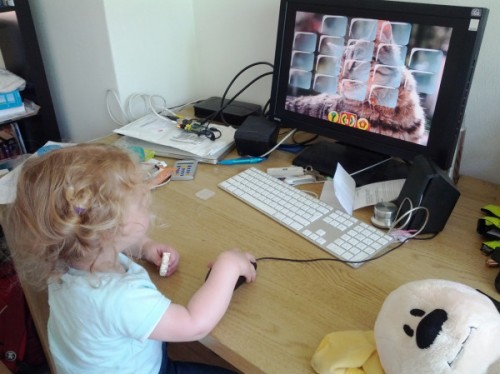
September is wellness month at Digital Making at Home. Your young makers can code along with our educators every week to create projects that focus on their well-being. This week’s brand-new projects are all about helping young people concentrate better.
Through Digital Making at Home, we invite parents and kids all over the world to code and make along with us and our new projects, videos, and live streams every week.
This week’s live stream will take place on Wednesday at 5.30pm BST / 12.30pm EDT / 10.00pm IST at rpf.io/home. Let your kids join in so they can progress to the next stage of learning to code with Scratch!
If you’re in the USA, your young people can join Christina on Thursday at 3.30pm PDT / 5.30pm CDT / 6.30pm EDT for an additional US-time live stream! Christina will show newcomers how to begin coding Scratch projects. Thanks to our partners Infosys Foundation USA for making this new live stream possible.
Picture the scene: you have a Raspberry Pi configured to run on your network, you power it up headless (without a monitor), and now you need to know which IP address it was assigned.
Matthias came up with this solution, which makes your Raspberry Pi blink its IP address, because he used a Raspberry Pi Zero W headless for most of his projects and got bored with having to look it up with his DHCP server or hunt for it by pinging different IP addresses.
How does it work?
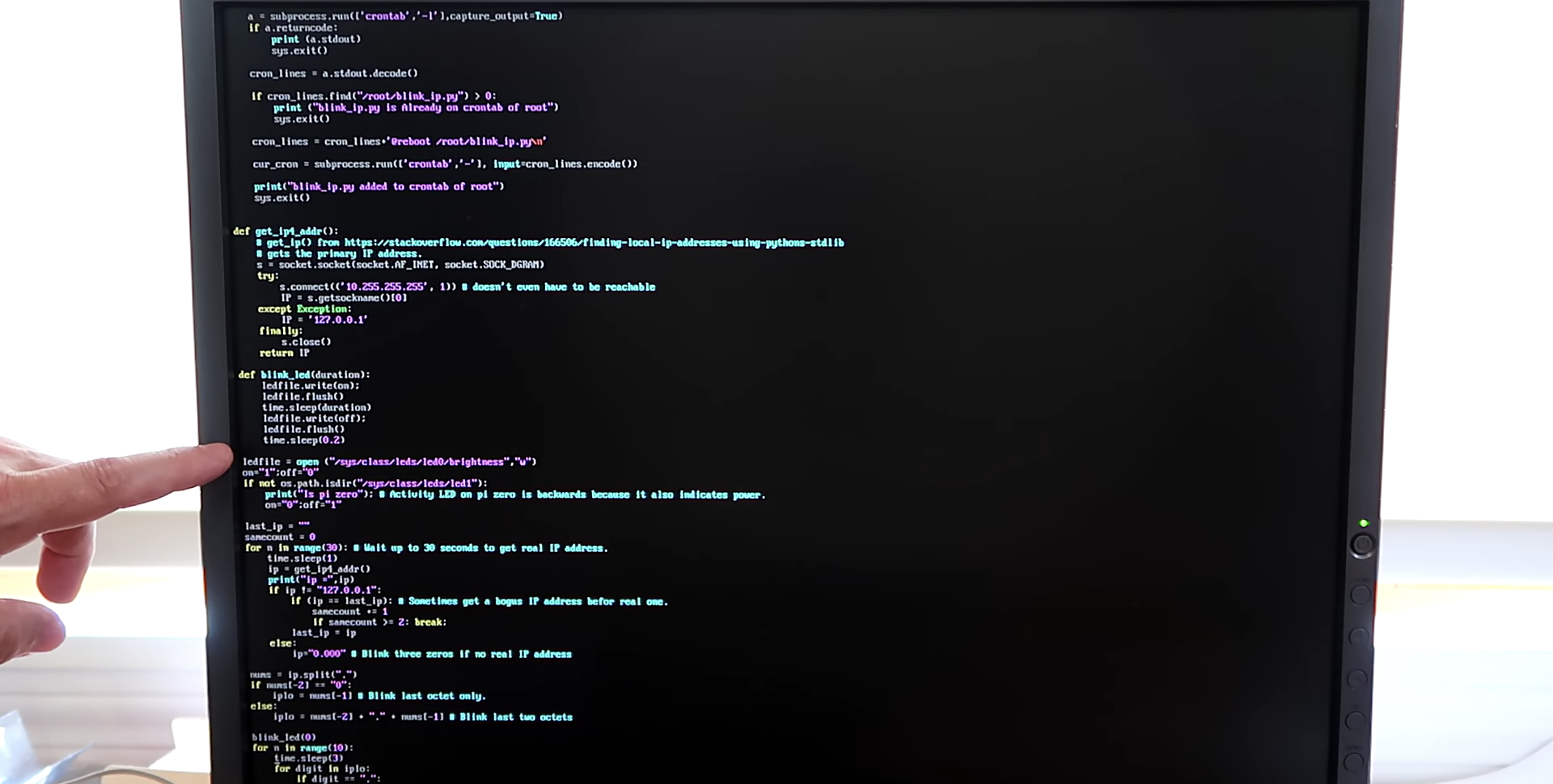
A script runs when you start your Raspberry Pi and indicates which IP address is assigned to it by blinking it out on the device’s LED. The script comprises about 100 lines of Python, and you can get it on GitHub.
Easy peasy GitHub breezy
The power/status LED on the edge of the Raspberry Pi blinks numbers in a Roman numeral-like scheme. You can tell which number it’s blinking based on the length of the blink and the gaps between each blink, rather than, for example, having to count nine blinks for a number nine.
Blinking in Roman numerals
Short, fast blinks represent the numbers one to four, depending on how many short, fast blinks you see. A gap between short, fast blinks means the LED is about to blink the next digit of the IP address, and a longer blink represents the number five. So reading the combination of short and long blinks will give you your device’s IP address.
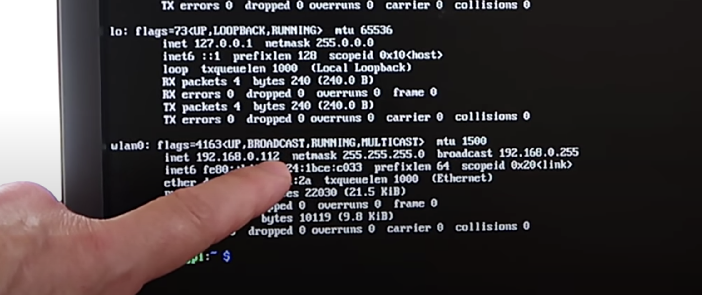
You can see this in action at this exact point in the video. You’ll see the LED blink fast once, then leave a gap, blink fast once again, then leave a gap, then blink fast twice. That means the device’s IP address ends in 112.
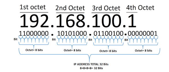
What are octets?
Luckily, you usually only need to know the last three numbers of the IP address (the last octet), as the previous octets will almost always be the same for all other computers on the LAN.
The script blinks out the last octet ten times, to give you plenty of chances to read it. Then it returns the LED to its default functionality.
Which LED on which Raspberry Pi?
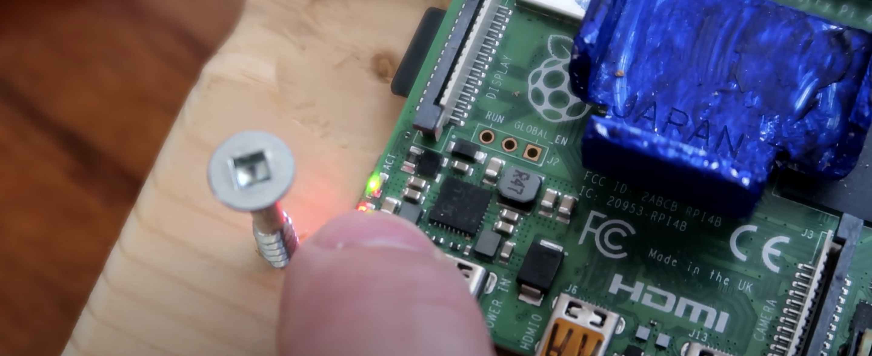
On a Raspberry Pi Zero W, the script uses the green status/power LED, and on other Raspberry Pis it uses the green LED next to the red power LED.
The green LED blinking the IP address (the red power LED is slightly hidden by Matthias’ thumb)
Once you get the hang of the Morse code-like blinking style, this is a really nice quick solution to find your device’s IP address and get on with your project.
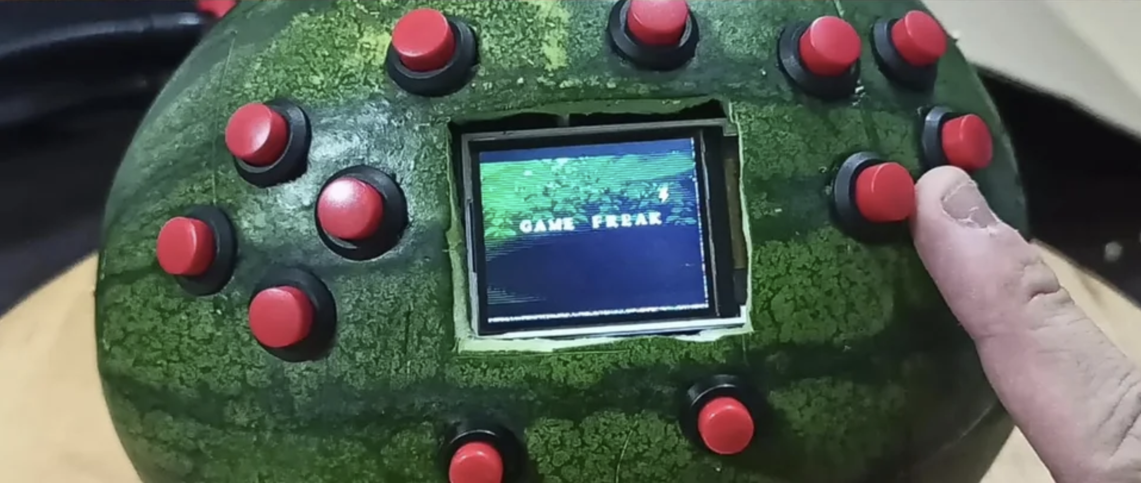
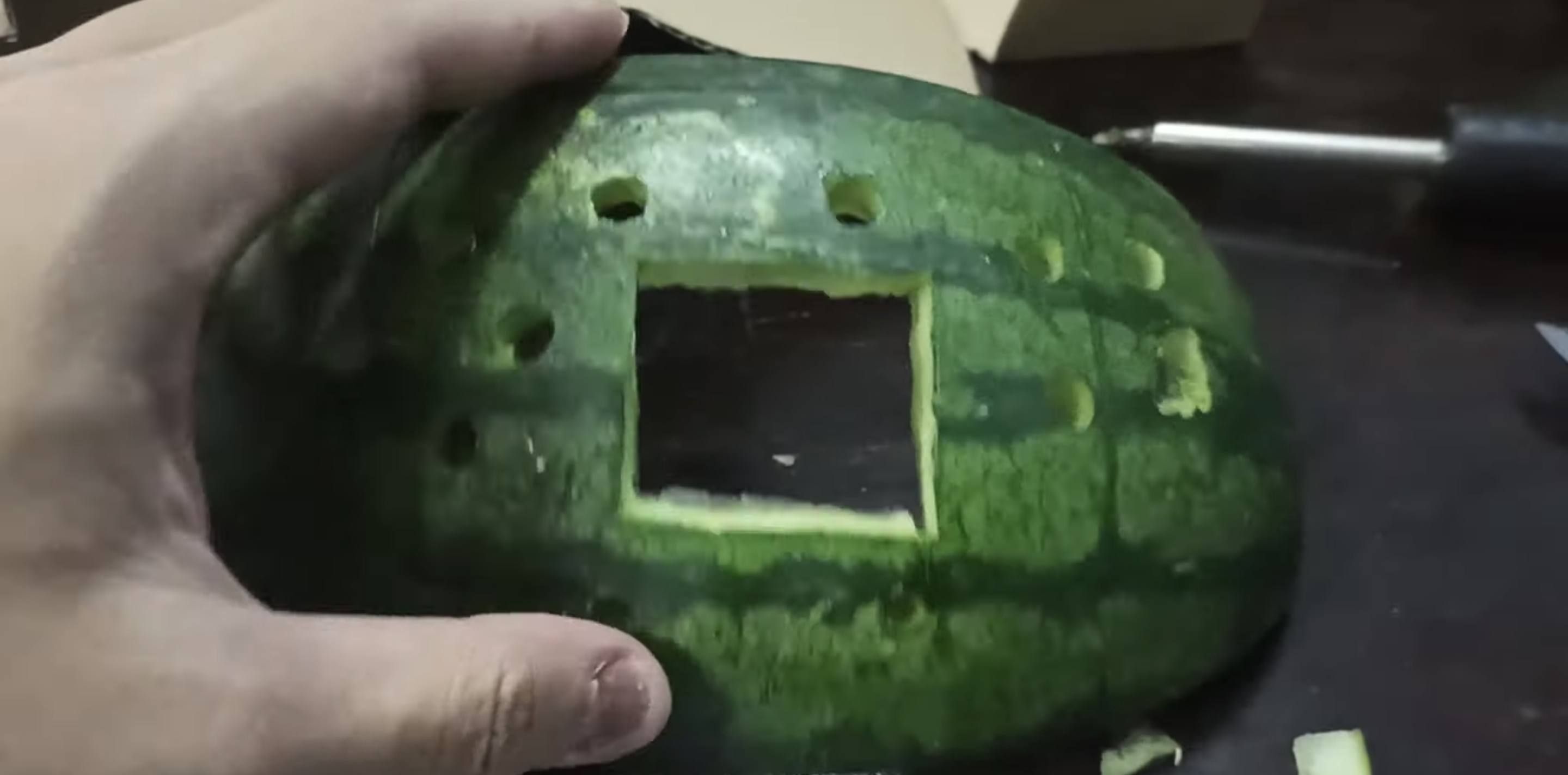
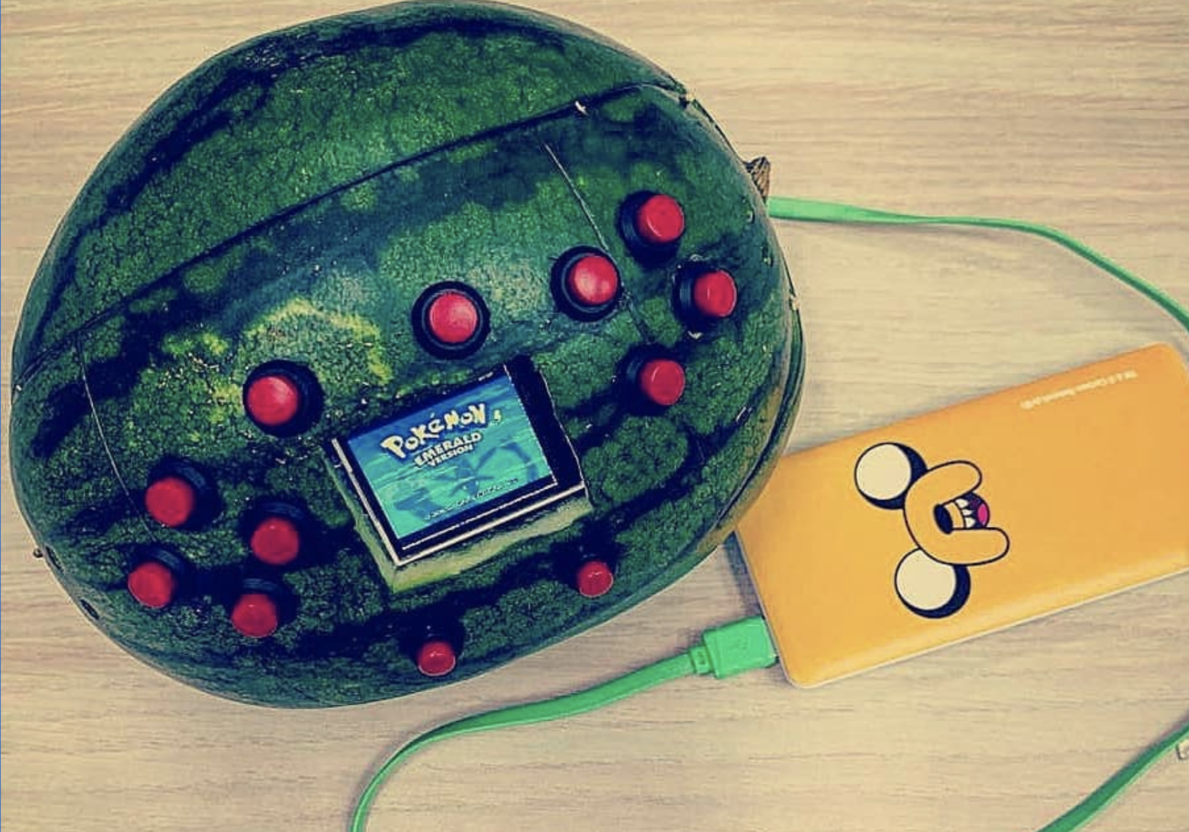
OK Cedrick, we don’t need to know why, but we have to know how you turned a watermelon into a games console.
This has got to be a world first. What started out as a regular RetroPie project has blown up reddit due to the unusual choice of casing for the games console: nearly 50,000 redditors upvoted this build within a week of Cedrick sharing it.
Jingo Dot power bank (that yellow thing you can see below)
Speakers
Buttons
Small 1.8″ screen
Cedric’s giggling really makes this video
Retropie
While this build looks epic, it isn’t too tricky to make. First, Cedrick flashed the RetroPie image onto an SD card, then he wired up a Raspberry Pi’s GPIO pins to the red console buttons, speakers, and the screen.
Cedrick achieved audio output by adding just a few lines of code to the config file, and he downloaded libraries for screen configuration and button input. That’s it! That’s all you need to get a games console up and running.
Cedrick just hanging on the train with his WaterBoy
Now for the messy bit
Cedrick had to gut an entire watermelon before he could start getting all the hardware in place. He power-drilled holes for the buttons to stick through, and a Stanley knife provided the precision he needed to get the right-sized gap for the screen.
Rather than drill even more holes for the speakers, Cedrick stuck them in place inside the watermelon using toothpicks. He did try hot glue first but… yeah. Turns out fruit guts are impervious to glue.
Moisture was going to be a huge problem, so to protect all the hardware from the watermelon’s sticky insides, Cedric lined it with plastic clingfilm.
Infinite lives
And here’s how you can help: Cedrick is open to any tips as to how to preserve the perishable element of his project: the watermelon. Resin? Vaseline? Time machine? How can he keep the watermelon fresh?
Share your ideas on reddit or YouTube, and remember to subscribe to see more of Cedric’s maverick making in the wild.
NODE has long been working to create open-source resources to help more people harness the decentralised internet, and their easily 3D-printed designs are perfect to optimise your Raspberry Pi.
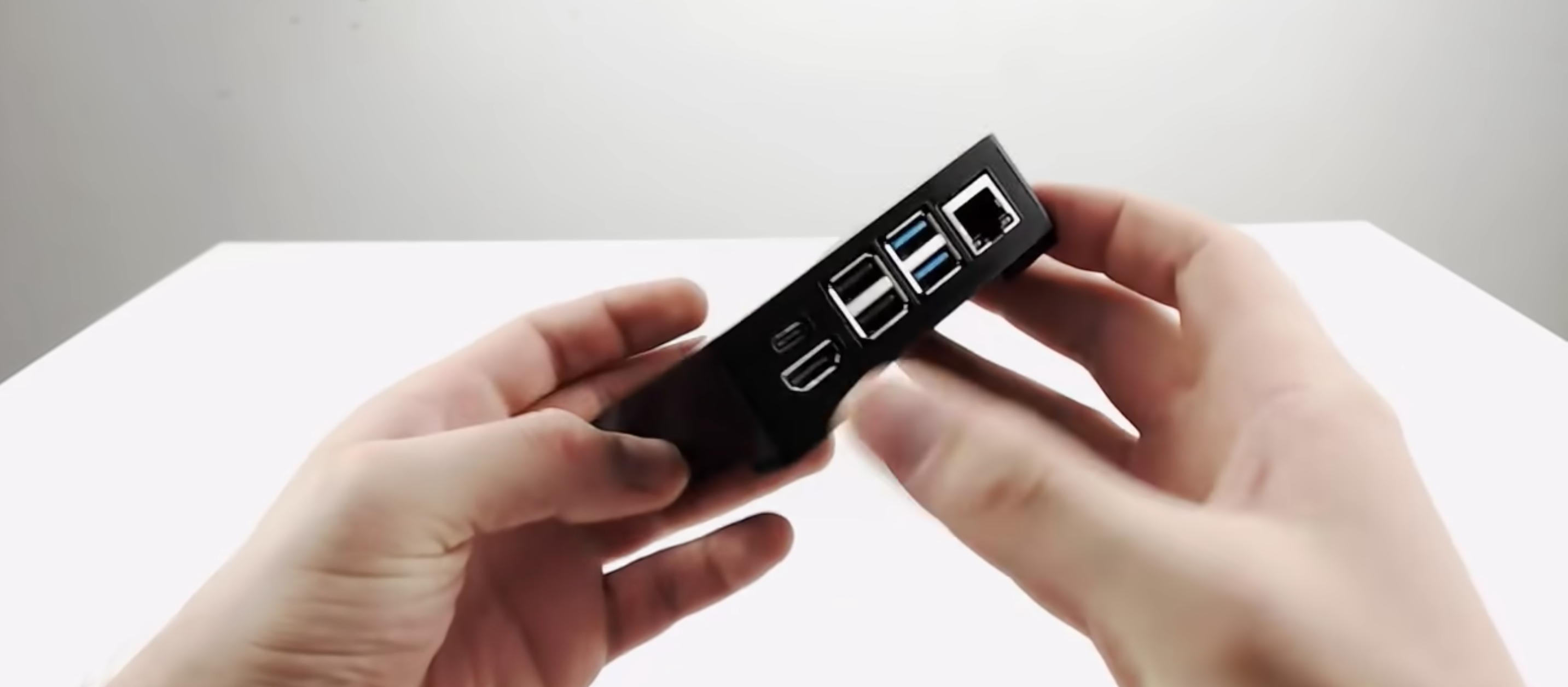
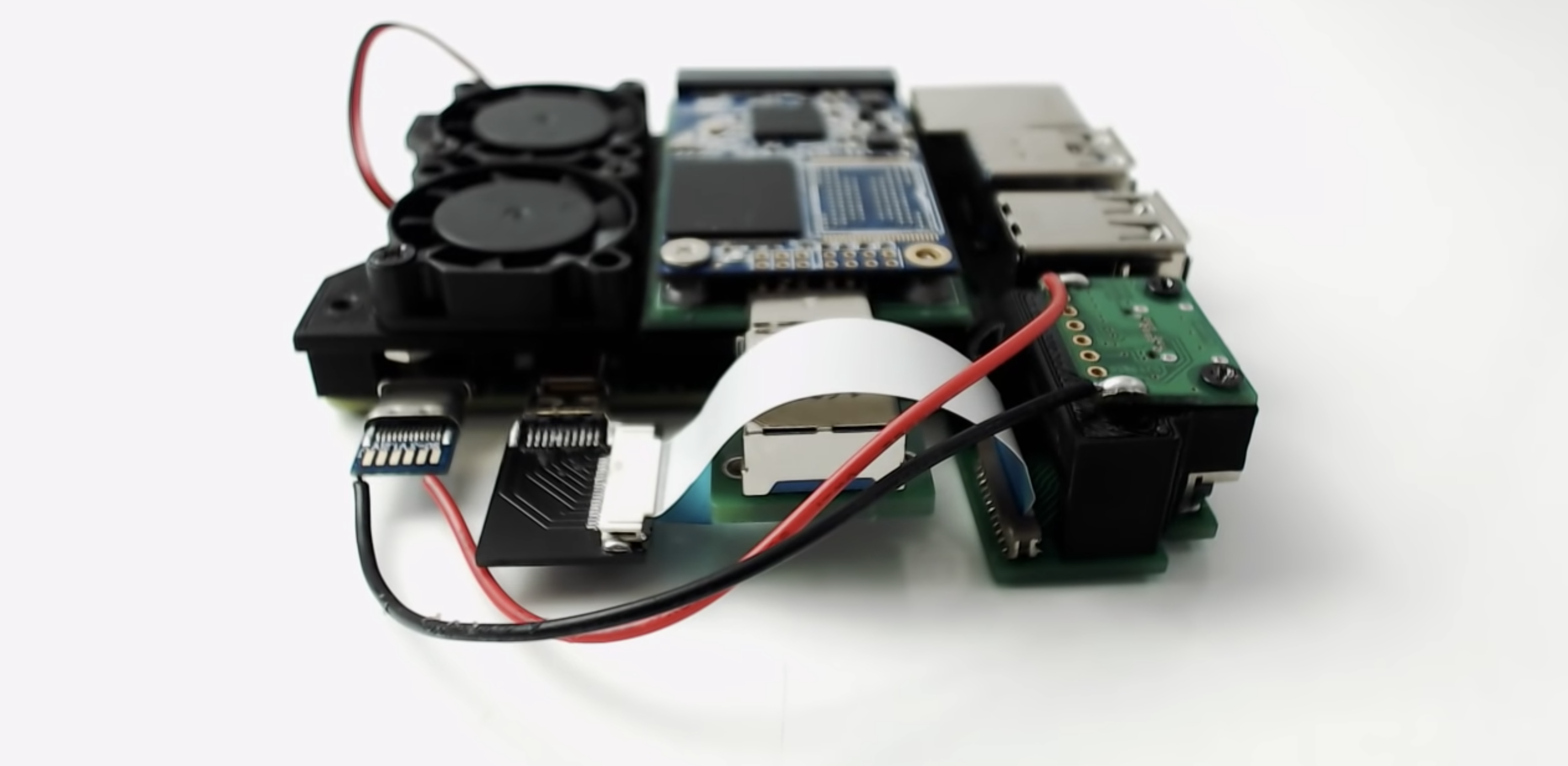
NODE wanted to take advantage of the faster processor and up to 8GB RAM on Raspberry Pi 4 when it came out last year. Now that our tiny computer is more than capable of being used as as a general Linux desktop system, the NODE Mini Server version 3 has been born.
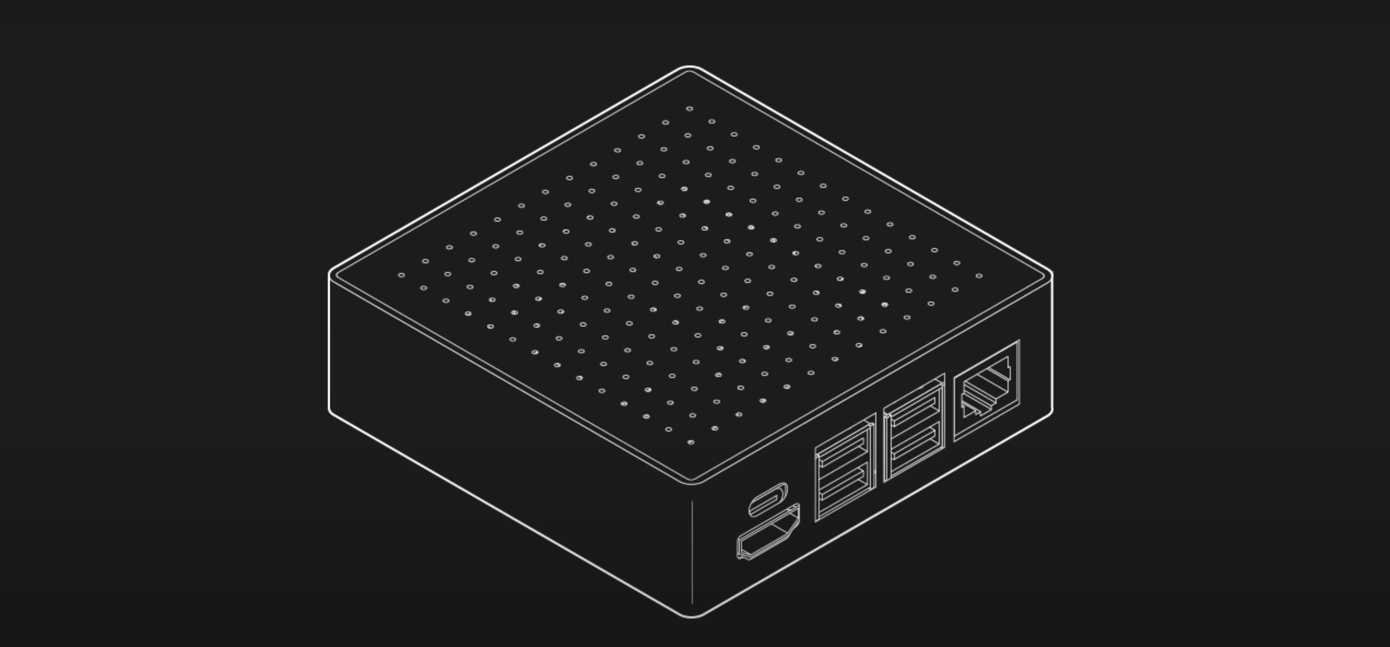
As for previous versions of NODE’s Mini Server, one of their main goals for this new iteration was to package Raspberry Pi in a way which makes it a little easier to use as a regular mini server or computer. In other words, it’s put inside a neat little box with all the ports accessible on one side.
Black is incredibly slimming
Slimmer and simpler
The latest design is simplified compared to previous versions. Everything lives in a 92mm × 92mm enclosure that isn’t much thicker than Raspberry Pi itself.
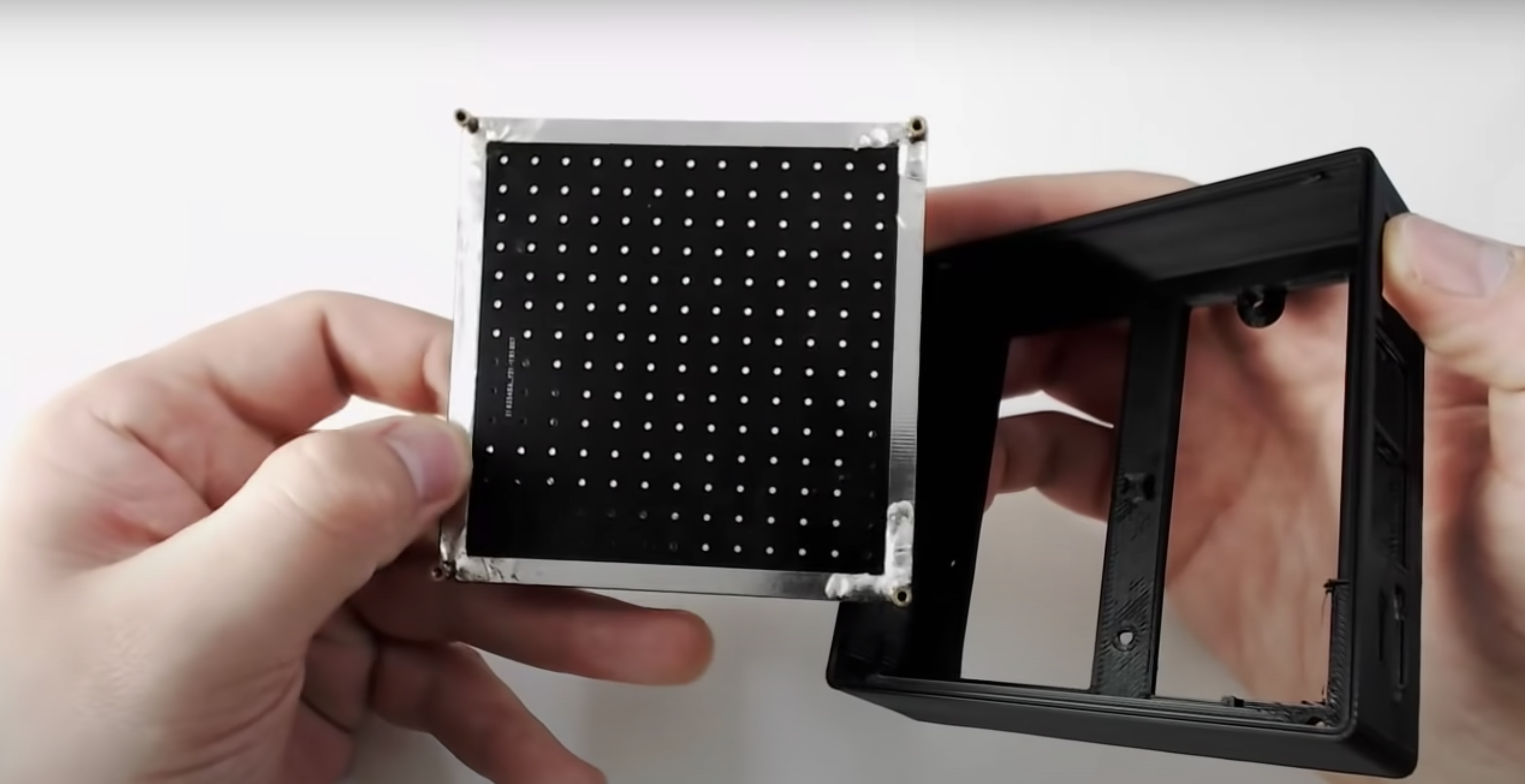
The slimmed-down new case comprises a single 3D-printed piece and a top cover made from a custom-designed printed circuit board (PCB) that has four brass-threaded inserts soldered into the corners, giving you a simple way to screw everything together.
The custom PCB cover
What are the new features?
Another goal for version 3 NODE’s Mini Server was to include as much modularity as possible. That’s why this new mini server requires no modifications to the Raspberry Pi itself, thanks to a range of custom-designed adapter boards. How to take advantage of all these new features is explained at this point in NODE’s YouTube video.
Ooh, shiny and new and new and shiny
Just like for previous versions, all the files and a list of the components you need to create your own Mini Server are available for free on the NODE website.
Leave comments on NODE’s YouTube video if you’d like to create and sell your own Mini Server kits or pre-made servers. NODE is totally open to showcasing any add-ons or extras you come up with yourself.
Looking ahead, making the Mini Server stackable and improving fan circulation is next on NODE’s agenda.
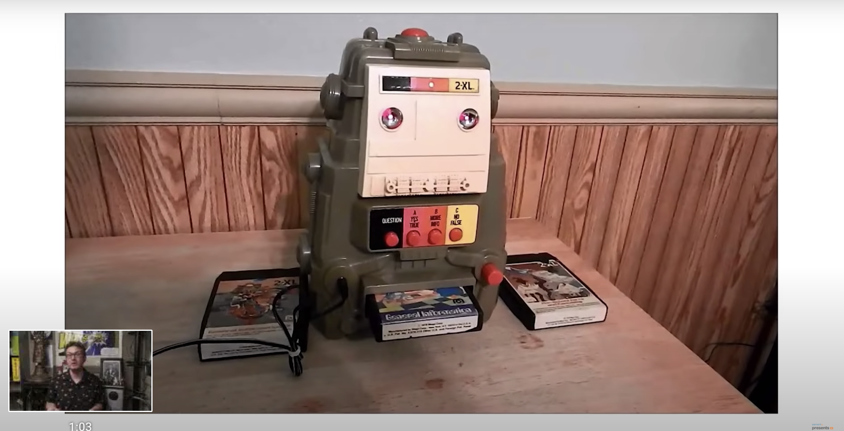
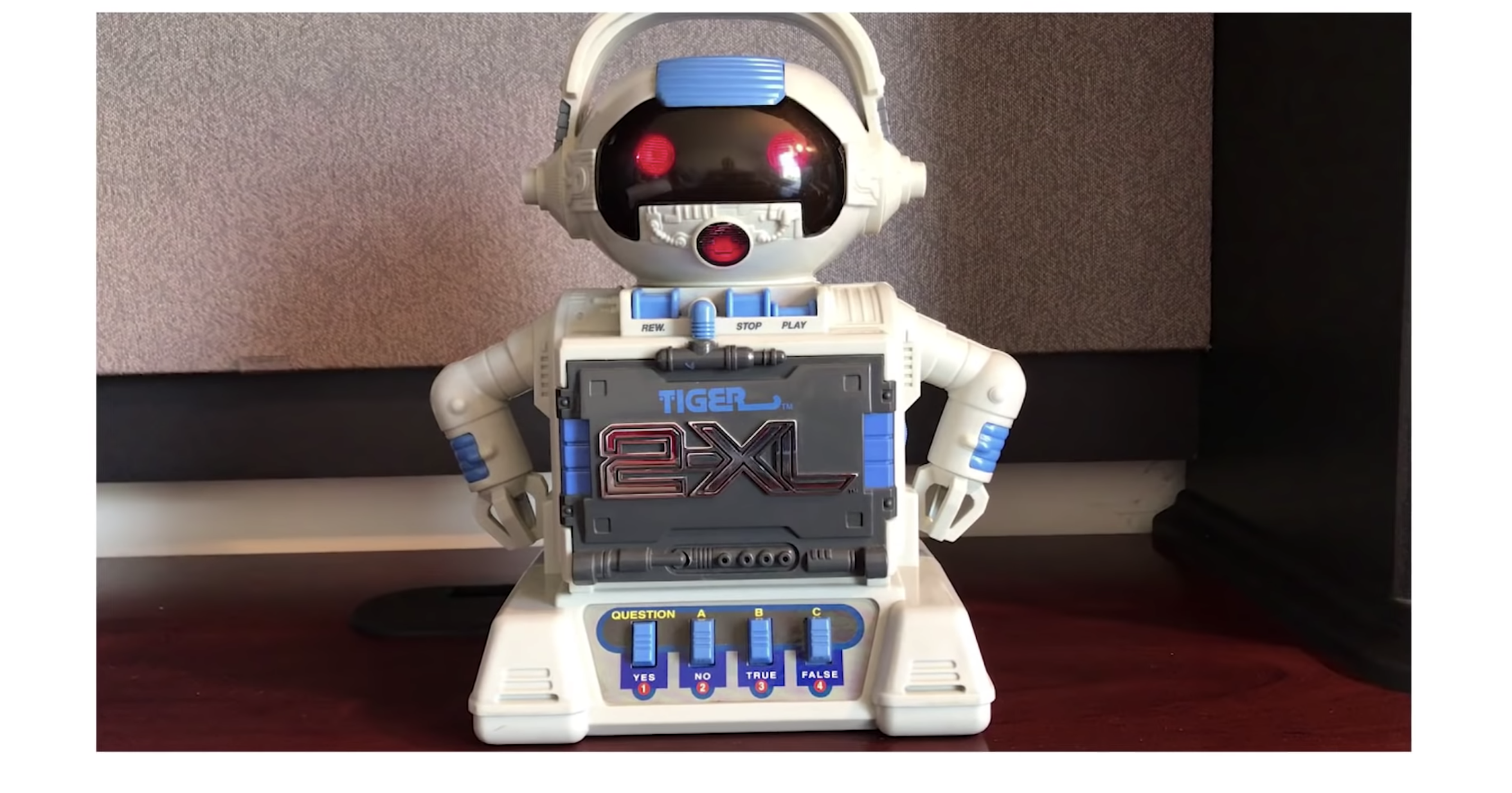
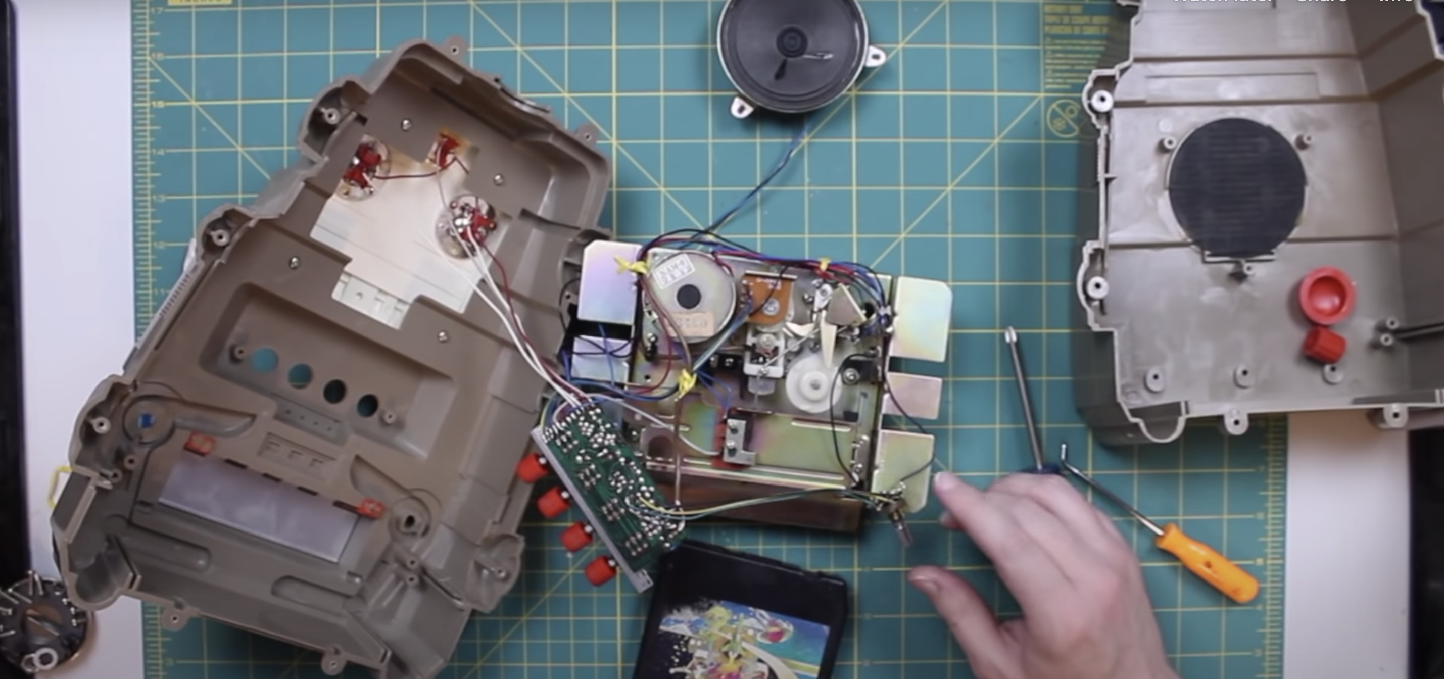
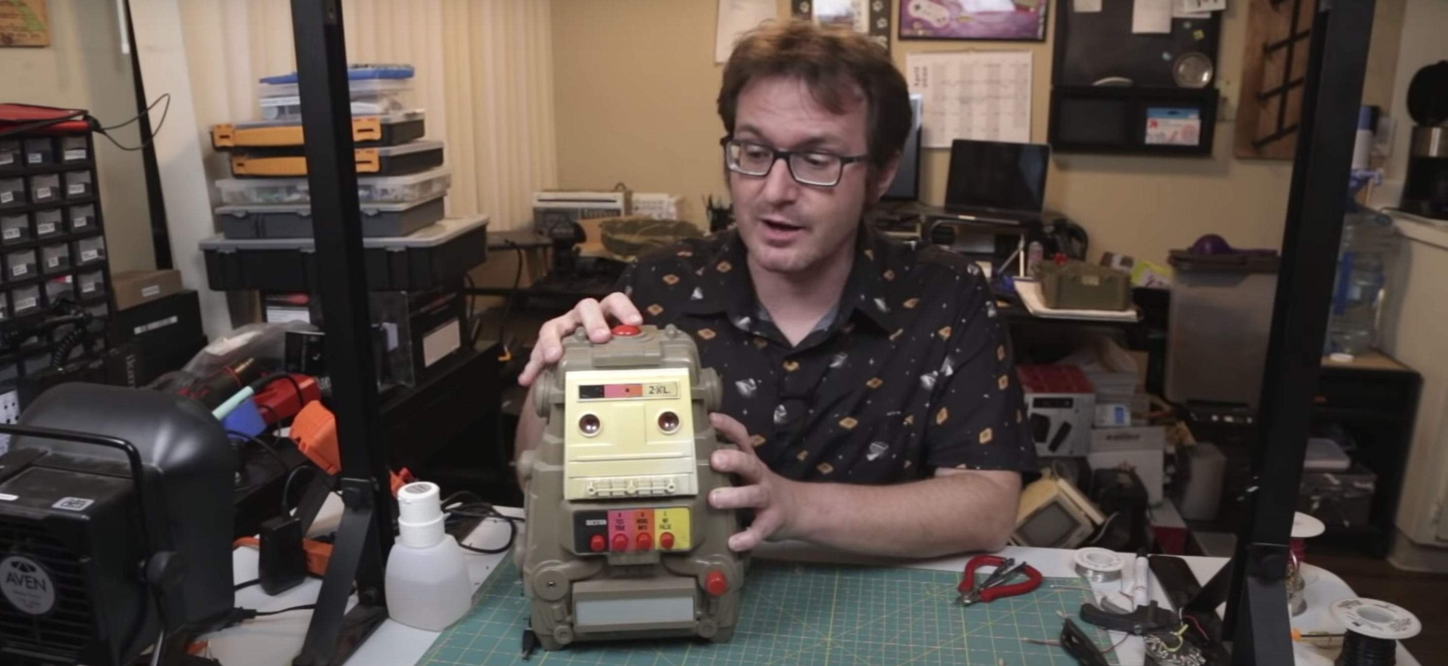
Do you feel weird asking the weather or seeking advice from a faceless device? Would you feel better about talking to a classic 1978 2-XL educational robot from Mego Corporation? Matt over at element14 Community, where tons of interesting stuff happens, has got your back.
Watch Matt explain how the 2-XL toy robot worked before he started tinkering with it. This robot works with Google Assistant on a Raspberry Pi, and answers to a custom wake word.
Our recent blog about repurposing a Furby as a voice assistant device would have excited Noughties kids, but this one is mostly for our beautiful 1970s- and 1980s-born fanbase.
Time travel
2-XL, Wikipedia tells us, is considered the first “smart toy”, marketed way back in 1978, and exhibiting “rudimentary intelligence, memory, gameplay, and responsiveness”. 2-XL had a personality that kept kids’ attention, telling jokes and offering verbal support as they learned.
Teardown
Delve under the robot’s armour to see how the toy was built, understand the basic working mechanism, and watch Matt attempt to diagnose why his 2-XL is not working.
Setting up Google Assistant
The Matrix Creator daughter board mentioned in the kit list is an ideal platform for developing your own AI assistant. It’s the daughter board’s 8-microphone array that makes it so brilliant for this task. Learn how to set up Google Assistant on the Matrix board in this video.
What if you don’t want to wake your retrofit voice assistant in the same way as all the other less dedicated users, the ones who didn’t spend hours of love and care refurbishing an old device? Instead of having your homemade voice assistant answer to “OK Google” or “Alexa”, you can train it to recognise a phrase of your choice. In this tutorial, Matt shows you how to set up a custom wake word with your voice assistant, using word detection software called Snowboy.
Keep an eye on element14 on YouTube for the next instalment of this excellent retrofit project.
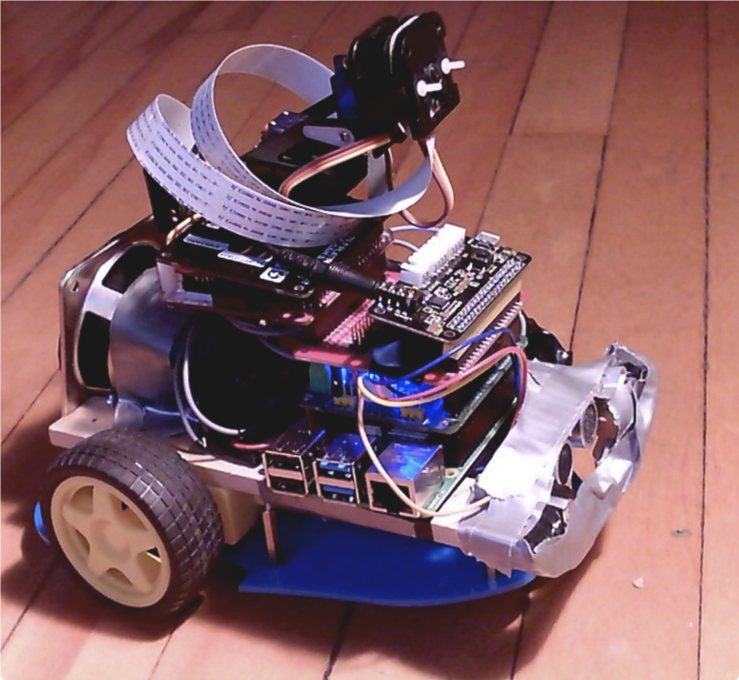
Nandu Vadakkath was inspired by a line-following robot built (literally) entirely from salvage materials that could wait patiently and purchase beer for its maker in Tamil Nadu, India. So he set about making his own, but with the goal of making it capable of slightly more sophisticated tasks.
Robot comes when called, and recognises you as its special human
Software
Nandu had ambitious plans for his robot: navigation, speech and listening, recognition, and much more were on the list of things he wanted it to do. And in order to make it do everything he wanted, he incorporated a lot of software, including:
Robot shares Nandu’s astrological chart
Python 3
virtualenv, a tool for creating isolating virtual Python environments
the OpenCV open source computer vision library
the spaCy open source natural language processing library
the TensorFlow open source machine learning platform
Haar cascade algorithms for object detection
A ResNet neural network with the COCO dataset for object detection
DeepSpeech, an open source speech-to-text engine
eSpeak NG, an open source speech synthesiser
The MySQL database service
So how did Nandu go about trying to make the robot do some of the things on his wishlist?
Context and intents engine
The engine uses spaCy to analyse sentences, classify all the elements it identifies, and store all this information in a MySQL database. When the robot encounters a sentence with a series of possible corresponding actions, it weighs them to see what the most likely context is, based on sentences it has previously encountered.
Getting to know you
The robot has been trained to follow Nandu around but it can get to know other people too. When it meets a new person, it takes a series of photos and processes them in the background, so it learns to remember them.
There she blows!
Speech
Nandu didn’t like the thought of a basic robotic voice, so he searched high and low until he came across the MBROLA UK English voice. Have a listen in the videos above!
Object and people detection
The robot has an excellent group photo function: it looks for a person, calculates the distance between the top of their head and the top of the frame, then tilts the camera until this distance is about 60 pixels. This is a lot more effort than some human photographers put into getting all of everyone’s heads into the frame.
Nandu has created a YouTube channel for his robot companion, so be sure to keep up with its progress!
September is wellness month at Digital Making at Home. Your young makers can code along with our educators every week to create projects which focus on their well-being. This week’s brand new projects are all about embracing the things that make you feel calm. Go check them out!
Through Digital Making at Home, we invite parents and kids all over the world to code and make along with us and our new projects, videos, and live streams every week.
This week’s live stream will take place on Wednesday at 5.30pm BST / 12.30pm EDT / 10.00pm IST at rpf.io/home. Let your kids join in so they can progress to the next stage of learning to code with Scratch!
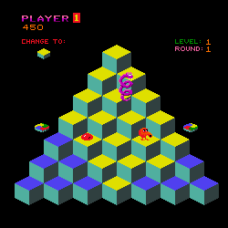
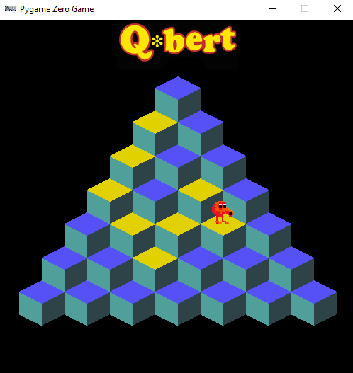
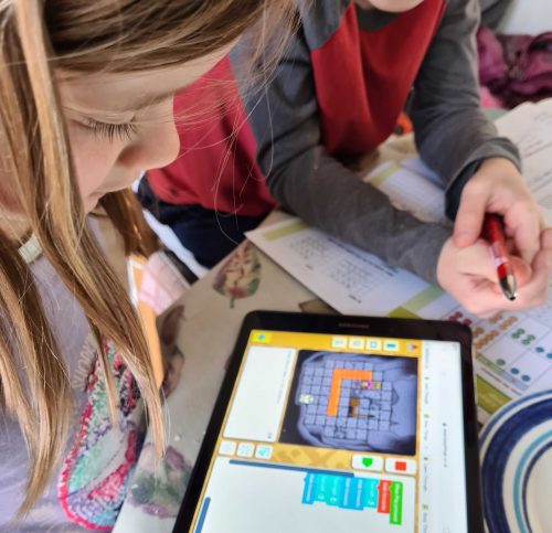
Code the mechanics of an eighties arcade hit in Python and Pygame Zero. Mark Vanstone shows you how
Players must change the colour of every cube to complete the level.
Late in 1982, a funny little orange character with a big nose landed in arcades. The titular Q*bert’s task was to jump around a network of cubes arranged in a pyramid formation, changing the colours of each as they went. Once the cubes were all the same colour, it was on to the next level; to make things more interesting, there were enemies like Coily the snake, and objects which helped Q*bert: some froze enemies in their tracks, while floating discs provided a lift back to the top of the stage.
Q*bert was designed by Warren Davis and Jeff Lee at the American company Gottlieb, and soon became such a smash hit that, the following year, it was already being ported to most of the home computer platforms available at the time. New versions and remakes continued to appear for years afterwards, with a mobile phone version appearing in 2003. Q*bert was by far Gottlieb’s most popular game, and after several changes in company ownership, the firm is now part of Sony’s catalogue – Q*bert’s main character even made its way into the 2015 film, Pixels.
Q*bert uses isometric-style graphics to draw a pseudo-3D display – something we can easily replicate in Pygame Zero by using a single cube graphic with which we make a pyramid of Actor objects. Starting with seven cubes on the bottom row, we can create a simple double loop to create the pile of cubes. Our Q*bert character will be another Actor object which we’ll position at the top of the pile to start. The game screen can then be displayed in the draw() function by looping through our 28 cube Actors and then drawing Q*bert.
Our homage to Q*bert. Try not to fall into the terrifying void.
We need to detect player input, and for this we use the built-in keyboard object and check the cursor keys in our update() function. We need to make Q*bert move from cube to cube so we can move the Actor 32 pixels on the x-axis and 48 pixels on the y-axis. If we do this in steps of 2 for x and 3 for y, we will have Q*bert on the next cube in 16 steps. We can also change his image to point in the right direction depending on the key pressed in our jump() function. If we use this linear movement in our move() function, we’ll see the Actor go in a straight line to the next block. To add a bit of bounce to Q*bert’s movement, we add or subtract (depending on the direction) the values in the bounce[] list. This will make a bit more of a curved movement to the animation.
Now that we have our long-nosed friend jumping around, we need to check where he’s landing. We can loop through the cube positions and check whether Q*bert is over each one. If he is, then we change the image of the cube to one with a yellow top. If we don’t detect a cube under Q*bert, then the critter’s jumped off the pyramid, and the game’s over. We can then do a quick loop through all the cube Actors, and if they’ve all been changed, then the player has completed the level. So those are the basic mechanics of jumping around on a pyramid of cubes. We just need some snakes and other baddies to annoy Q*bert – but we’ll leave those for you to add. Good luck!
Here’s Mark’s code for a Q*bert-style, cube-hopping platform game. To get it running on your system, you’ll need to install Pygame Zero. And to download the full code and assets, head here.
Get your copy of Wireframe issue 42
You can read more features like this one in Wireframe issue 42, available directly from Raspberry Pi Press — we deliver worldwide.
And if you’d like a handy digital version of the magazine, you can also download issue 42 for free in PDF format.
Make sure to follow Wireframe on Twitter and Facebook for updates and exclusive offers and giveaways. Subscribe on the Wireframe website to save up to 49% compared to newsstand pricing!
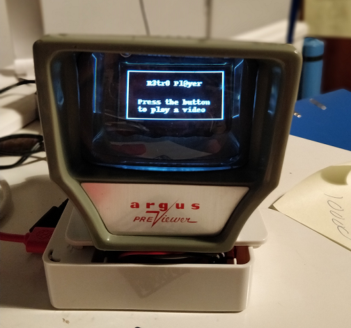
We found this project at TeCoEd and we loved the combination of an OLED display housed inside a retro Argus slide viewer. It uses a Raspberry Pi 3 with Python and OpenCV to pull out single frames from a video and write them to the display in real time.
TeCoEd names this creation the Raspberry Pi Retro Player, or RPRP, or – rather neatly – RP squared. The Argus viewer, he tells us, was a charity-shop find that cost just 50p. It sat collecting dust for a few years until he came across an OLED setup guide on hackster.io, which inspired the birth of the RPRP.
Timelapse of the build and walk-through of the code
At the heart of the project is a Raspberry Pi 3 which is running a Python program that uses the OpenCV computer vision library. The code takes a video clip and breaks it down into individual frames. Then it resizes each frame and converts it to black and white, before writing it to the OLED display. The viewer sees the video play in pleasingly retro monochrome on the slide viewer.
Tiny but cute, like us!
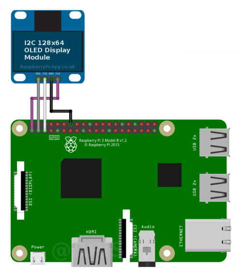
TeCoEd ran into some frustrating problems with the OLED display, which, he discovered, uses the SH1106 driver, rather than the standard SH1306 driver that the Adafruit CircuitPython library expects. Many OLED displays use the SH1306 driver, but it turns out that cheaper displays like the one in this project use the SH1106. He has made a video to spare other makers this particular throw-it-all-in-the-bin moment.
Tutorial for using the SH1106 driver for cheap OLED displays
TeCoEd is, as ever, our favourite kind of maker – the sharing kind! He has collated everything you’ll need to get to grips with OpenCV, connecting the SH1106 OLED screen over I2C, and more. He’s even told us where we can buy the OLED board.
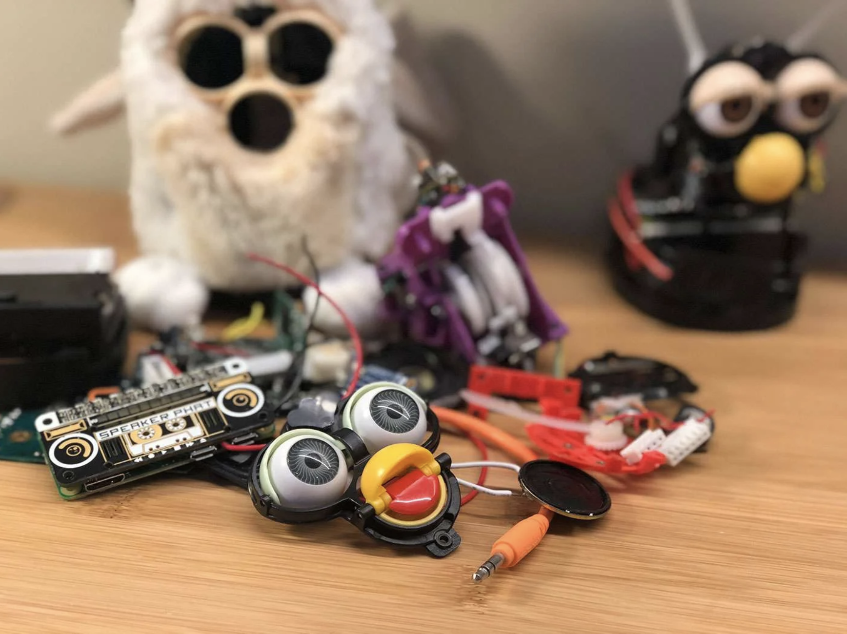
How can you turn a redundant, furry, slightly annoying tech pet into a useful home assistant? Zach took to howchoo to show you how to combine a Raspberry Pi Zero W with Amazon’s Alexa Voice Service software and a Furby to create Furlexa.
Furby was pretty impressive technology, considering that it’s over 20 years old. It could learn to speak English, sort of, by listening to humans. It communicated with other Furbies via infrared sensor. It even slept when its light sensor registered that it was dark.
Furby innards, exploded
Zach explains why Furby is so easy to hack:
Furby is comprised of a few primary components — a microprocessor, infrared and light sensors, microphone, speaker, and — most impressively — a single motor that uses an elaborate system of gears and cams to drive Furby’s ears, eyes, mouth and rocker. A cam position sensor (switch) tells the microprocessor what position the cam system is in. By driving the motor at varying speeds and directions and by tracking the cam position, the microprocessor can tell Furby to dance, sing, sleep, or whatever.
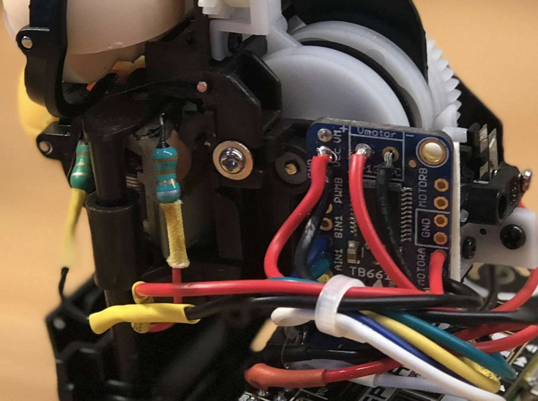
The original CPU and related circuitry were replaced with a Raspberry Pi Zero W
Zach continues: “Though the microprocessor isn’t worth messing around with (it’s buried inside a blob of resin to protect the IP), it would be easy to install a small Raspberry Pi computer inside of Furby, use it to run Alexa, and then track Alexa’s output to make Furby move.”
The Raspberry Pi is running Alexa Voice Service (AVS) to provide full Amazon Echo functionality. Amazon AVS doesn’t officially support the tiny Raspberry Pi Zero, so lots of hacking was required. Point 10 on Zach’s original project walkthrough explains how to get AVS working with the Pimoroni Speaker pHAT.
Animating Furby
A small motor driver board is connected to the Raspberry Pi’s GPIO pins, and controls Furby’s original DC motor and gearbox: when Alexa speaks, so does Furby. The Raspberry Pi Zero can’t supply enough juice to power the motor, so instead, it’s powered by Furby’s original battery pack.
Software
There are three key pieces of software that make Furlexa possible:
Amazon Alexa on Raspberry Pi – follow the instructions on this Github page to set this up.
A script to control Furby’s motor – howchooer Tyler wrote the Python script that Zach is using to drive the motor, and you can copy and paste it from Zach’s howchoo walkthrough.
A script that detects when Alexa is speaking and calls the motor program – Furby detects when Alexa is speaking by monitoring the contents of a file whose contents change when audio is being output. Zach has written a separate guide for driving a DC motor based on Linux sound output.
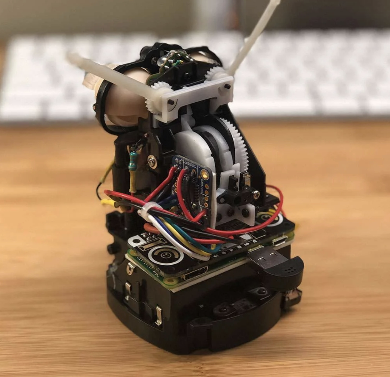
Teeny tiny living space
The real challenge was cramming the Raspberry Pi Zero plus the Speaker pHAT, the motor controller board, and all the wiring back inside Furby, where space is at a premium. Soldering wires directly to the GPIO saved a bit of room, and foam tape holds everything above together nice and tightly. It’s a squeeze!
Through Digital Making at Home, we invite your and your kids all over the world to code and make along with us and our new videos every week.
Since March, we’ve created over 20 weeks’ worth of themed code-along videos for families to have fun with and learn at home. Here are some of our favourite themes — get coding with us today!
If you’ve never coded before…
Follow along with our code-along video released this week and make a digital stress ball with us. In the video, we’ve got 6-year-old Noah trying out coding for the first time!
Code fun video games
Creating your own video games is a super fun, creative way to start coding and learn what it’s all about.
Check out our code-along videos and projects where we show you:
Digital making isn’t all about video games and robots! You can use it to create truly artistic projects as well. So come and explore with us as we show you:
Have your kids never coded before? Then out Digital Making at Home video this week is perfect for you to get them started.
In our free code-along video this week, six-year-old Noah codes his first Scratch project guided by Marc from our team. The project is a digital stress ball, because our theme for September is wellness and looking after ourselves.
Through Digital Making at Home, we invite parents and kids all over the world to code and make along with us and our new videos and live stream every week.
Our live stream will take place on Wednesday 5.30pm BST / 12.30pm EDT / 10.00pm IST at rpf.io/home. Let your kids join in so they can progress to the next stage of learning to code with Scratch!
YouTuber extraordinaire Ahad Cove HATES taking out the rubbish, so he decided to hack a rubbish bin/trash can – let’s go with trash can from now on – to take itself out to be picked up.
Sounds simple enough? The catch is that Ahad wanted to create an AI that can see when the garbage truck is approaching his house and trigger the garage door to open, then tell the trash can to drive itself out and stop in the right place. This way, Ahad doesn’t need to wake up early enough to spot the truck and manually trigger the trash can to drive itself.
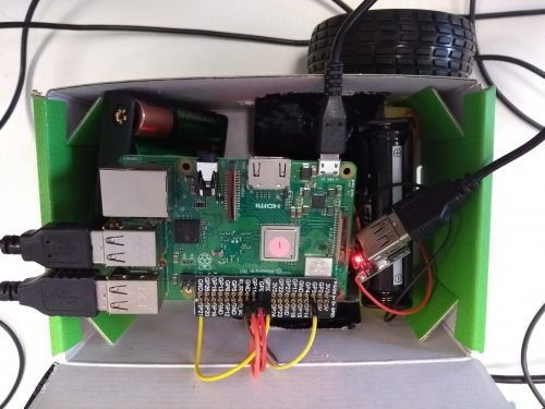
Hardware
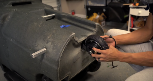
The trash can’s original wheels weren’t enough on their own, so Ahad brought in an electronic scooter wheel with a hub motor, powered by a 36V lithium ion battery, to guide and pull them. Check out this part of the video to hear how tricky it was for Ahad to install a braking system using a very strong servo motor.
The new wheel sits at the front of the trash can and drags the original wheels at the back along with
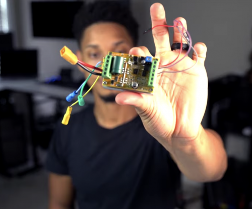
An affordable driver board controls the speed, power, and braking system of the garbage can.
The driver board
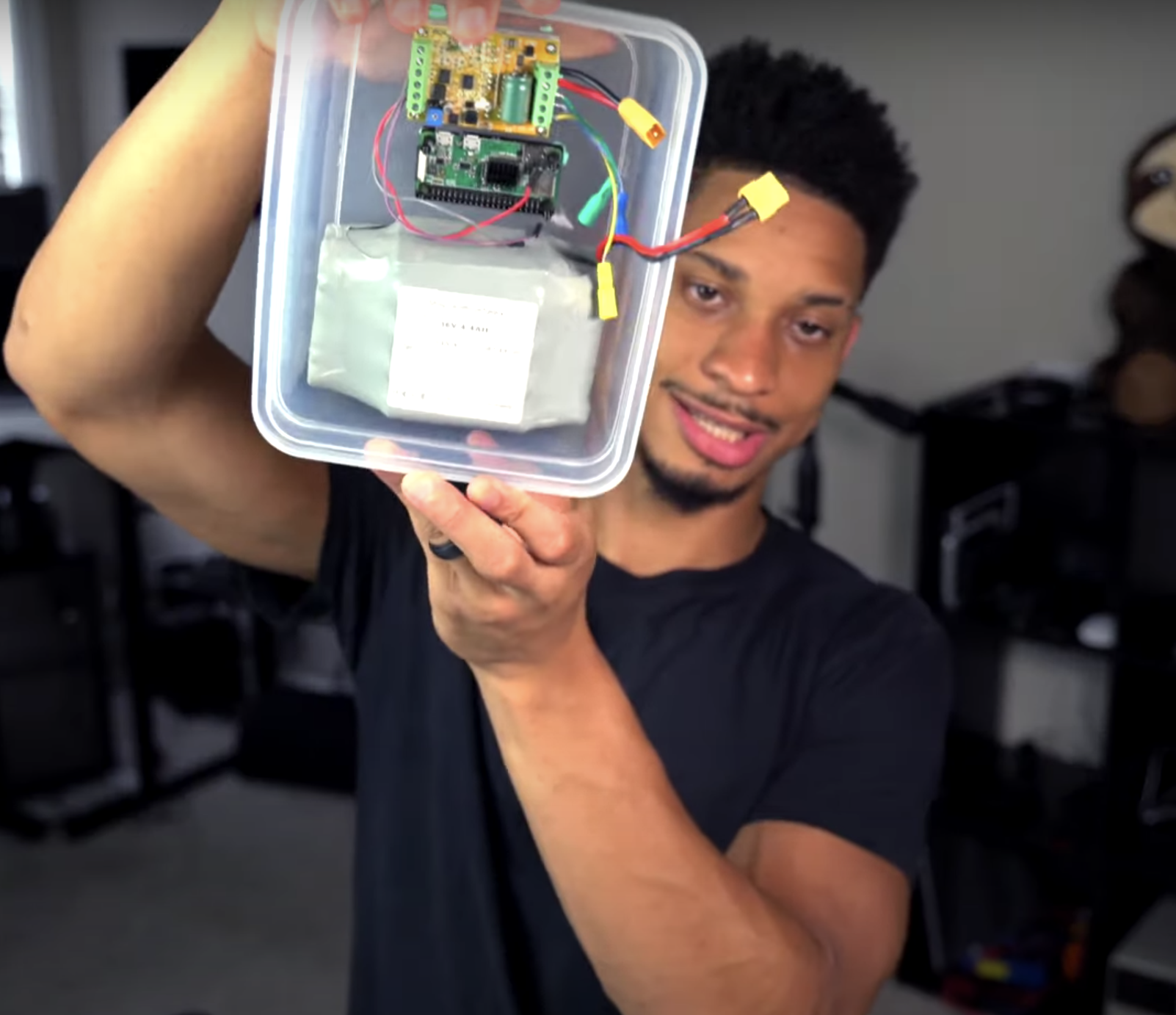
Tying everything together is a Raspberry Pi 3B+. Ahad uses one of the GPIO pins on the Raspberry Pi to send the signal to the driver board. He started off the project with a Raspberry Pi Zero W, but found that it was too fiddly to get it to handle the crazy braking power needed to stop the garbage can on his sloped driveway.
The Raspberry Pi Zero W, which ended up getting replaced in an upgrade
Everything is kept together and dry with a plastic snap-close food container Ahad lifted from his wife’s kitchen collection. Ssh, don’t tell.
Software
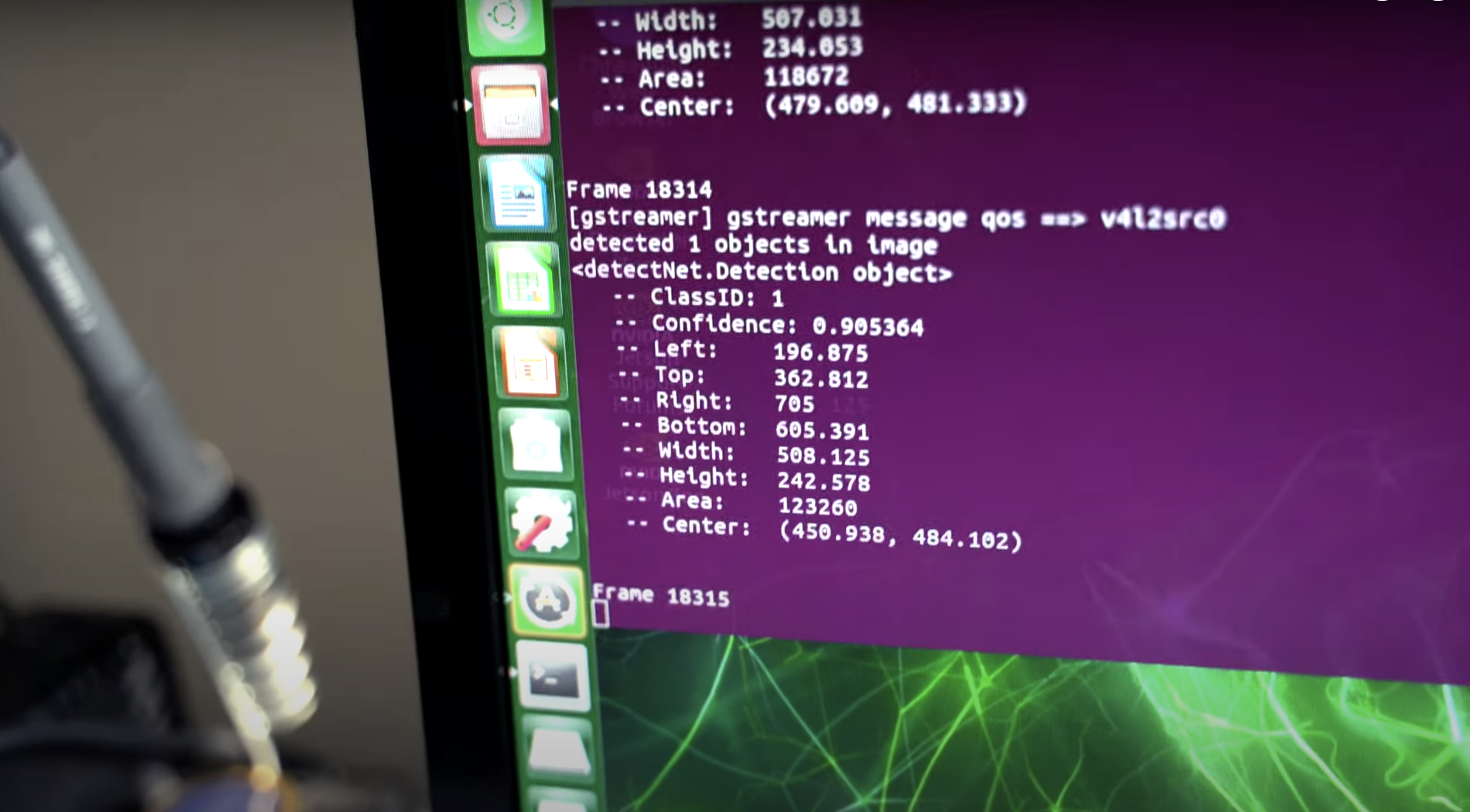
Ahad uses an object detection machine learning model to spot when the garbage truck passes his house. He handles this part of the project with an Nvidia Jetson Xavier NX board, connected to a webcam positioned to look out of the window watching for garbage trucks.
Object detected!
Opening the garage door
Ahad’s garage door has a wireless internet connection, so he connected the door to an app that communicates with his home assistant device. The app opens the garage door when the webcam and object detection software see the garbage truck turning into his street. All this works with the kit inside the trash can to get it to drive itself out to the end of Ahad’s driveway.
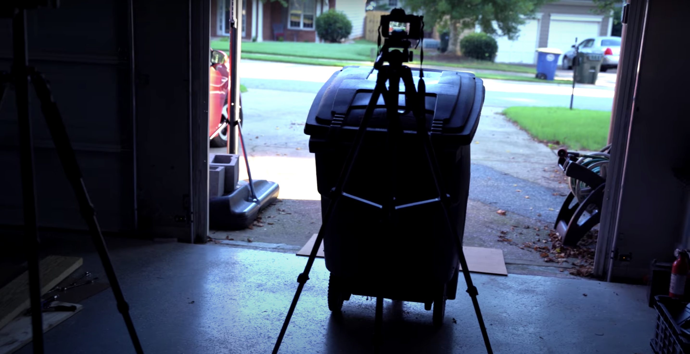
There she goes! (With her homemade paparazzi setup behind her)
Check out the end of Ahad’s YouTube video to see how human error managed to put a comical damper on the maiden voyage of this epic build.
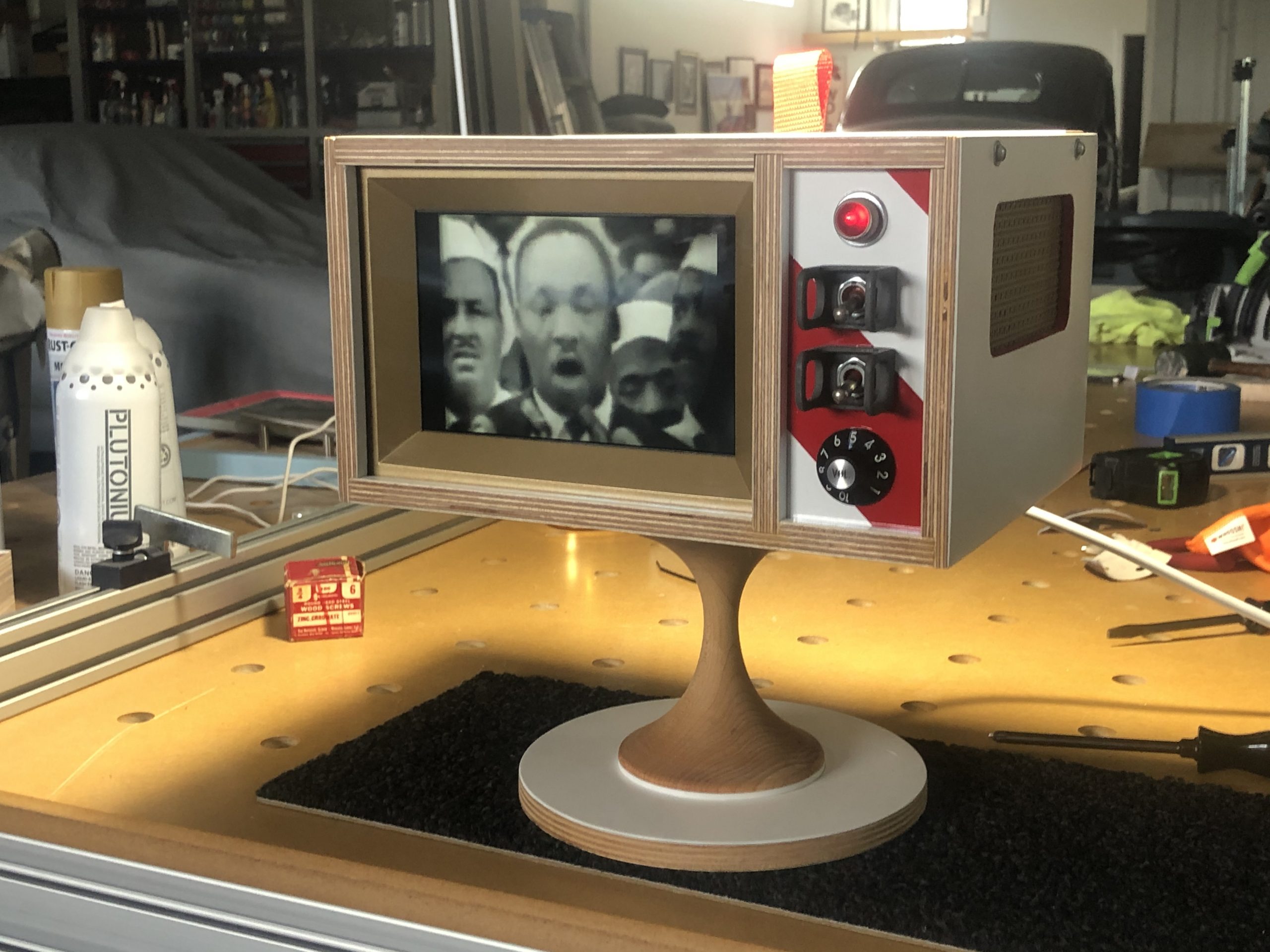
Nothing on television worth watching? Ryan Cochran’s TV set is just as visually arresting when it’s turned off, as David Crookes reports in the latest issue of the MagPi magazine, out now.
Flat-screen televisions, with their increasingly thin bezels, are designed to put the picture front and centre. Go back a few decades, however, and a number of TVs were made to look futuristic – some even sported space age designs resembling astronaut helmets or flying saucers sat upon elaborate stands. They were quirky and hugely fun.
Maker Ryan Cochran’s project evokes such memories of the past. “I have a passion for vintage modern design and early NASA aesthetics, and I wanted to make something which would merge the two into an art piece that could fit on my shelf,” he recalls. “The first thing I could think of was a small television.” And so the idea for the Atomic TV came into being.
Made of wood and using spare tech parts left over from a couple of past projects, it’s a television that’s as compelling to look at when it’s turned off as when it’s playing videos on a loop. “My main concern was fit and finish,” he says. “I didn’t want this thing to look amateurish at all. I wanted it to look like a professionally built prototype from 1968.”
Turn on
Before he began planning the look of the project, Ryan wanted to make sure everything would connect. “The parts sort of drove the direction of the project, so the first thing I did was mock everything up without a cabinet to make sure everything worked together,” he says.
This posed some problems. “The display is 12 volts, and I would have preferred to simplify things by using one of the 5-volt displays on the market, but I had what I had, so I figured a way to make it work,” Ryan explains, discovering the existence of a dual 5 V-12 V power supply.
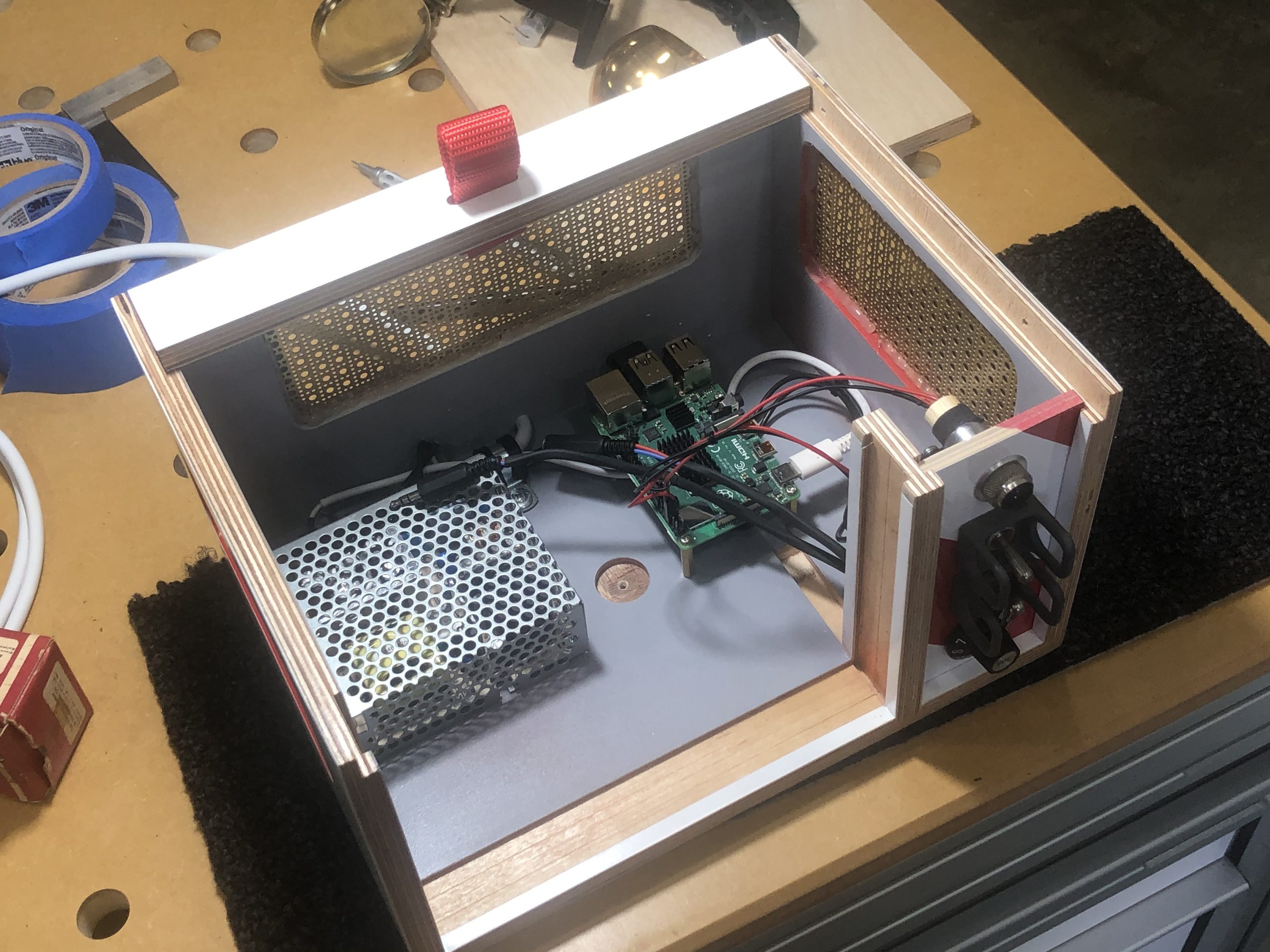
With a Raspberry Pi 4 computer, the LCD display, a driver board, and a pair of USB speakers borrowed from his son all firmly in hand, he worked on a way of controlling the volume and connected everything up.
“Power comes in and goes to an on/off switch,” he begins. “From there, it goes to the dual voltage power supply with the 12 V running the display and the 5 V running Raspberry Pi 4 and the small amp for the speakers. Raspberry Pi runs Adafruit’s Video Looper script and pulls videos from a USB thumb drive. It’s really simple, and there are no physical controls other than on/off switch and volume.”
Tune in
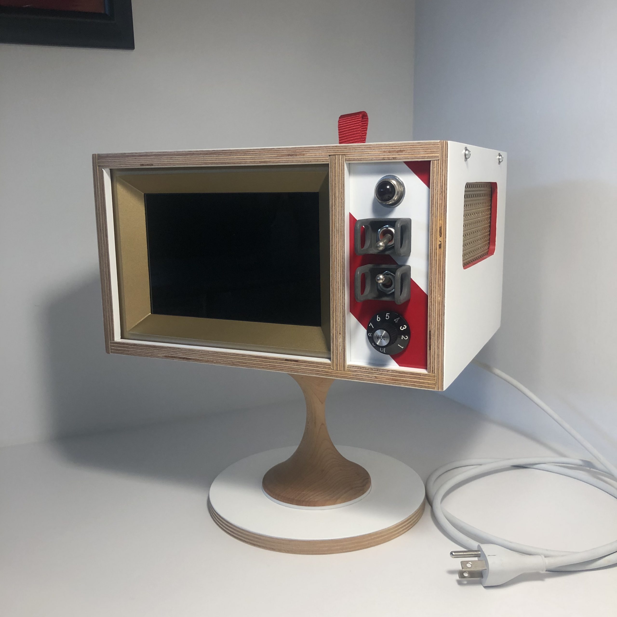
The bulk of the work came with the making of the project’s housing. “I wanted to nod the cap to Tom Sachs, an artist who does a lot of work I admire and my main concern was fit and finish,” Ryan reveals.
He filmed the process from start to end, showing the intricate work involved, including a base created from a cake-stand and a red-and-white panel for the controls. To ensure the components wouldn’t overheat, a fan was also included.
“The television runs 24/7 and it spends 99 percent of its time on mute,” says Ryan. “It’s literally just moving art that sits on my shelf playing my favourite films and video clips and, every now and then, I’ll look over, notice a scene I love, and turn up the volume to watch for a few minutes. It’s a great way to relax your brain and escape reality every now and then.”
Earlier this year, we released the Raspberry Pi High Quality Camera, a brand-new 12.3 megapixel camera that allows you to use C- and CS-mount lenses with Raspberry Pi boards.
We love it. You love it.
How do we know you love it? Because the internet is now full of really awesome 3D-printable cases and add-ons our community has created in order to use their High Quality Camera out and about…or for Octoprint…or home security…or SPACE PHOTOGRAPHY, WHAT?!
The moon, captured by a Raspberry Pi High Quality Camera. Credit: Greg Annandale
We thought it would be fun to show you some of 3D designs we’ve seen pop up on sites like Thingiverse and MyMiniFactory, so that anyone with access to a 3D printer can build their own camera too!
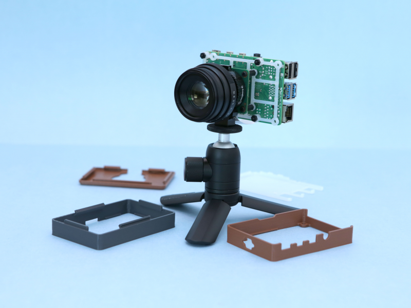
Adafruit did a thing, obvs
Shout out to our friends at Adafruit for this really neat, retro-looking camera case designed by the Ruiz Brothers. The brown filament used for the casing is so reminiscent of the leather bodies of SLRs from my beloved 1980s childhood that I can’t help but be drawn to it. And, with snap-fit parts throughout, you can modify this case model as you see fit. Not bad. Not bad at all.
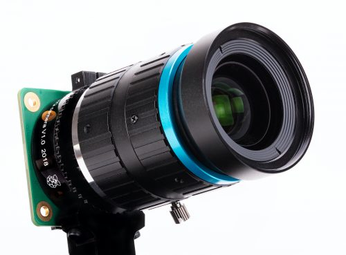
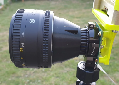
Nikon to Raspberry Pi
While the Raspberry Pi High Quality Camera is suitable for C- and CS-mount lenses out of the box, this doesn’t mean you’re limited to only these sizes! There’s a plethora of C- and CS-mount adapters available on the market, and you can also 3D print your own adapter.
Thingiverse user UltiArjan has done exactly that and designed this adapter for using Nikon lenses with the High Quality Camera. Precision is key here to get a snug thread, so you may have to fiddle with your printer settings to get the right fit.
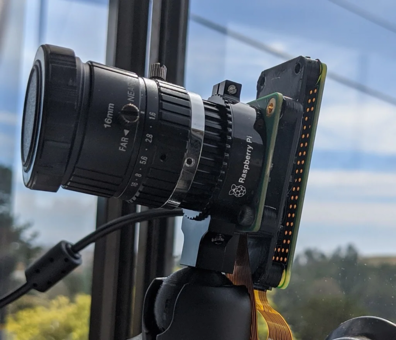
If you’re not interested in a full-body camera case and just need something to attach A to B, this minimal adapter for the Raspberry Pi Zero will be right up your street.
Designer ed7coyne put this model together in order to use Raspberry Pi Zero as a webcam, and according to Cura on my laptop, should only take about 2 hours to print at 0.1 with supports. In fact, since I’ve got Cura open already…
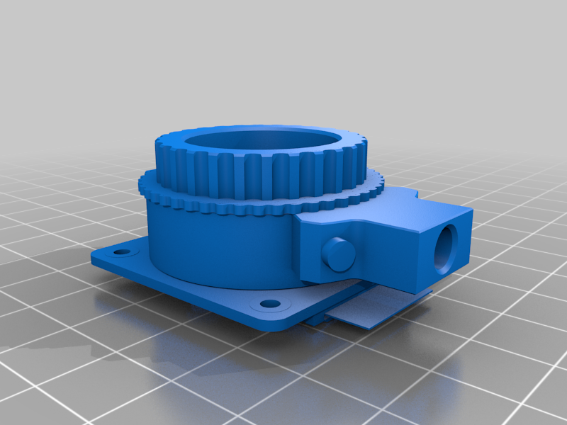
3D print a Raspberry Pi High Quality Camera?!
Not a working one, of course, but if you’re building something around the High Quality Camera and want to make sure everything fits without putting the device in jeopardy, you could always print a replica for prototyping!
Thingiverse user tmomas produced this scale replica of the Raspberry Pi High Quality Camera with the help of reference photos and technical drawings, and a quick search online will uncover similar designs for replicas of other Raspberry Pi products you might want to use while building a prototype
Bonus content alert
We made this video for HackSpace magazine earlier this year, and it’s a really hand resource if you’re new to the 3D printing game.
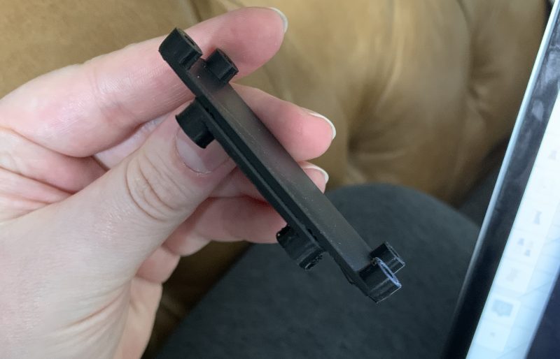
Also…
…I wasn’t lying when I said I was going to print ed7coyne’s minimal adapter.
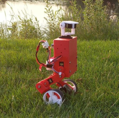
You in the community seemed so impressed with this recent Boston Dynamics–inspired build that we decided to feature another. This time, maker Harry was inspired by Boston Dynamics’ research robot Handle, which stands 6.5 ft tall, travels at 9 mph and jumps 4 feet vertically. Here’s how Harry made his miniature version, MABEL (Multi Axis Balancer Electronically Levelled).
MABEL has individually articulated legs to enhance off-road stability, prevent it from tipping, and even make it jump (if you use some really fast servos). Harry is certain that anyone with a 3D printer and a “few bits” can build one.
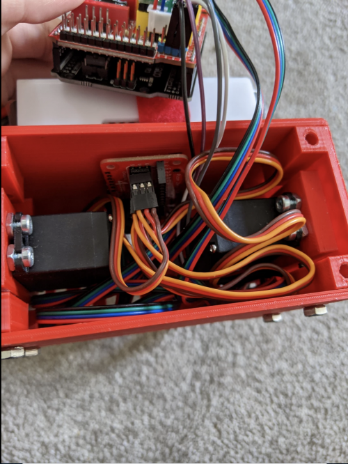
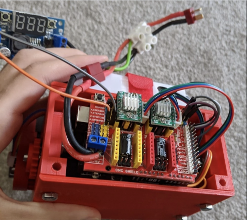
MABEL builds on the open-source YABR project for its PID controller, and it’s got added servos and a Raspberry Pi that helps interface them and control everything.
Installing MABEL’s Raspberry Pi brain and wiring the servos
Thanks to a program based on the open-source YABR firmware, an Arduino handles all of the PID calculations using data from an MPU-6050 accelerometer/gyro. Raspberry Pi, using Python code, manages Bluetooth and servo control, running an inverse kinematics algorithm to translate the robot legs perfectly in two axes.
The Raspberry Pi Zero W, servo controller, and IMUsit nicely underneath the Arduino stack
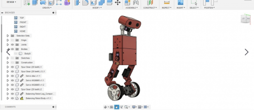
IKSolve is the class that handles the inverse kinematics functionality for MABEL (IKSolve.py) and allows for the legs to be translated using (x, y) coordinates. It’s really simple to use: all that you need to specify are the home values of each servo (these are the angles that, when passed over to your servos, make the legs point directly and straight downwards at 90 degrees).
When MABEL was just a twinkle in Harry’s eye
MABEL is designed to work by listening to commands on the Arduino (PID contoller) end that are sent to it by Raspberry Pi over serial using pySerial. Joystick data is sent to Raspberry Pi using the Input Python library. Harry first tried to get the joystick data from an old PlayStation 3 controller, but went with the PiHut’s Raspberry Pi Compatible Wireless Gamepad in the end for ease.
Keep up with Harry’s blog or give Raspibotics a follow on Twitter, as part 3 of his build write-up should be dropping imminently, featuring updates that will hopefully get MABEL jumping!
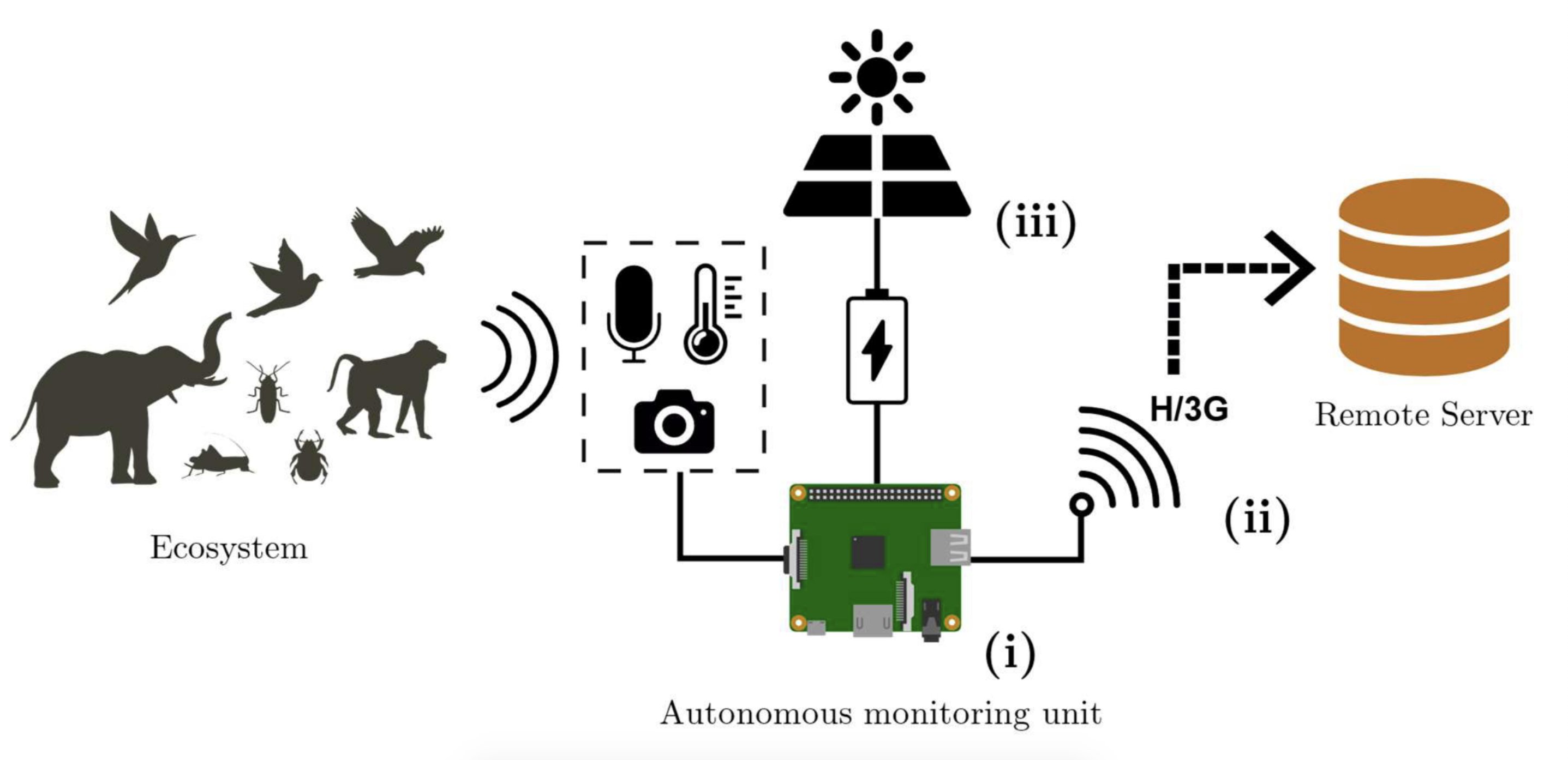
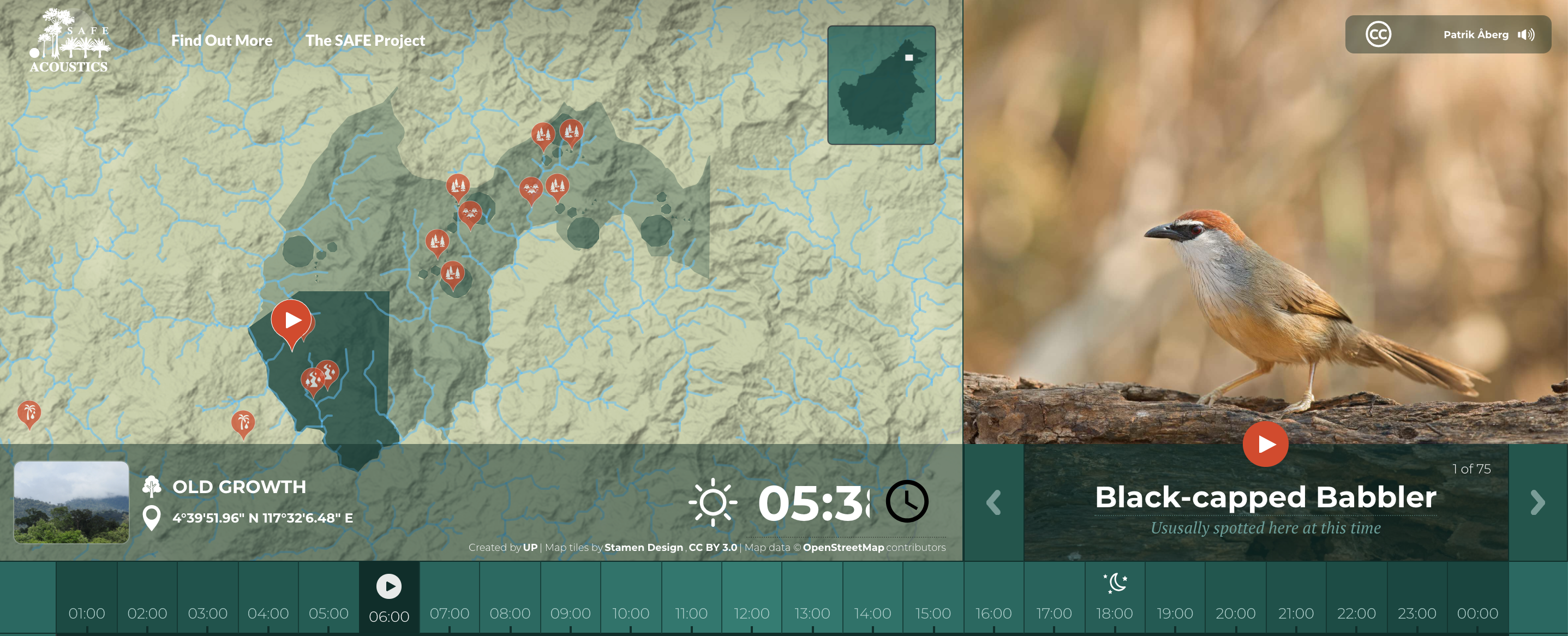
These award-winning, solar-powered audio recorders, built on Raspberry Pi, have been installed in the Borneo rainforest so researchers can listen to the local ecosystem 24/7. The health of a forest ecosystem can often be gaged according to how much noise it creates, as this signals how many species are around.
And you can listen to the rainforest too! The SAFE Acoustics website, funded by the World Wide Fund for Nature (WWF), streams audio from recorders placed around a region of the Bornean rainforest in Southeast Asia. Visitors can listen to live audio or skip back through the day’s recording, for example to listen to the dawn chorus.
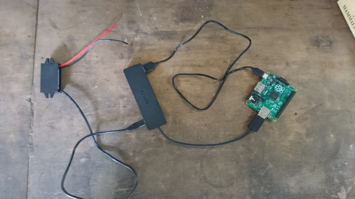
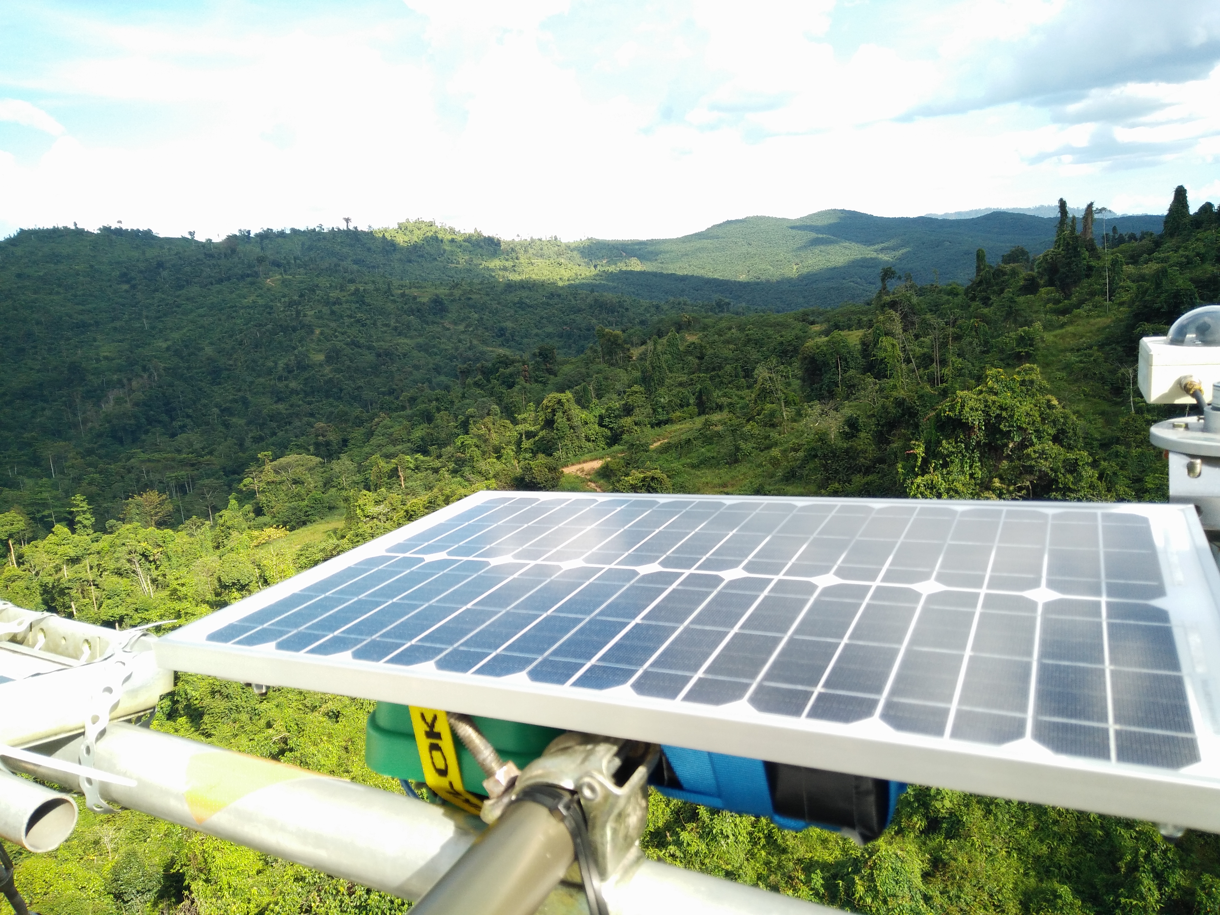
The device records data in the field and uploads it to a central server continuously and robustly over long time-periods. And it was built for around $305.
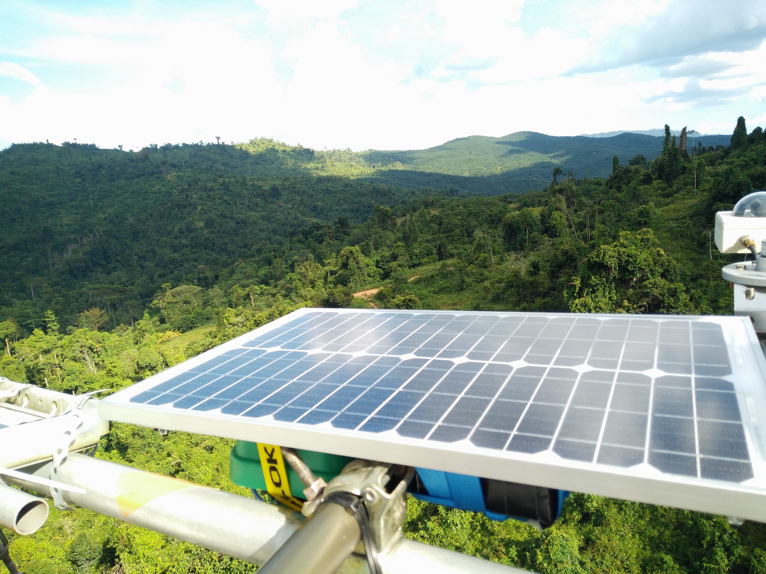
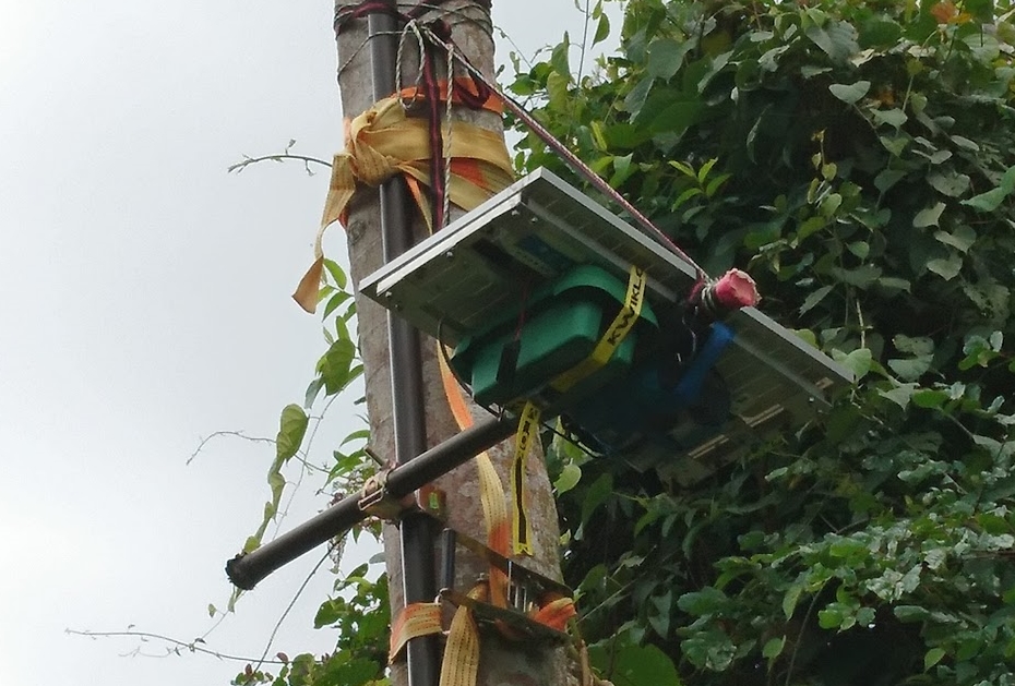
Here’s the full set up in the field. The Raspberry Pi-powered brains of the kit are safely inside the green box
The recorders have been installed by Imperial College London researchers as part of the SAFE Project – one of the largest ecological experiments in the world.
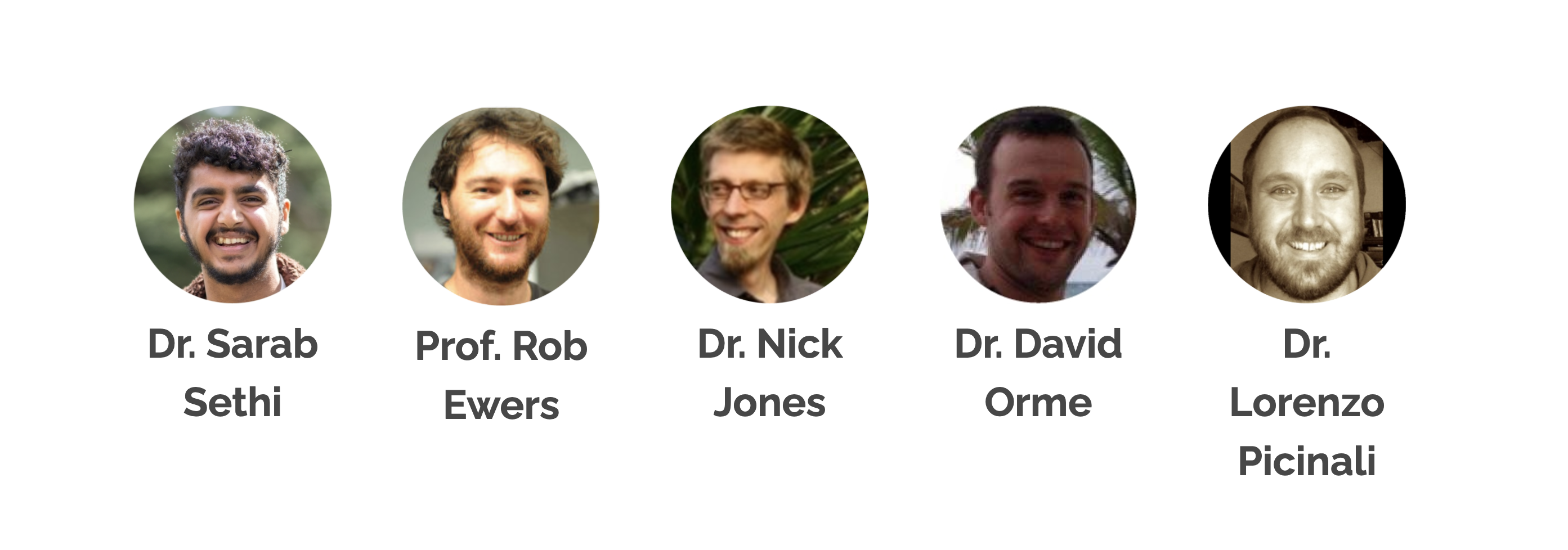
Dr Sarab Sethi designed the audio recorders with Dr Lorenzo Picinali. They wanted to quantify the changes in rainforest soundscape as land use changes, for example when forests are logged. Sarab is currently working on algorithms to analyse the gathered data with Dr Nick Jones from the Department of Mathematics.
The lovely cross-disciplinary research team based at Imperial College London
Join us for Digital Making at Home: this week, young people can find out how to create web pages with us! Through Digital Making at Home, we invite kids all over the world to code and make along with us and our new videos every week.
And tune in on Wednesday 2pm BST / 9am EDT / 7.30pm IST at rpf.io/home to code along with our live stream session and ask us all your question about the World Wide Web, the internet, and web development.


