We’re pleased to share that Dr Sue Sentance, our Chief Learning Officer, is receiving a Suffrage Science award for Mathematics and Computing today.
The Suffrage Science award scheme celebrates women in science. Sue is being recognised for her achievements in computer science and computing education research, and for her work promoting computing to the next generation.
Sue is an experienced teacher and teacher educator with an academic background in artificial intelligence, computer science, and education. She has made a substantial contribution to research in computing education in school over the last ten years, publishing widely on the teaching of programming, teacher professional development, physical computing, and curriculum change. In 2017 Sue received the BERA Public Engagement and Impact Award for her services to computing education. Part of Sue’s role at the Raspberry Pi Foundation is leading our Gender Balance in Computing research programme, which investigates ways to increase the number of girls and young women taking up computing at school level.
The awards are jewellery inspired by computing, mathematics, and the Suffragette movement
As Dr Hannah Dee, the previous award recipient who nominated Sue, says: “[…] The work she does is important — researchers need to look at what happens in schools, particularly when we consider gender. Girls are put off computing long before they get to universities, and an understanding of how children learn about computing and the ways in which we can support girls in tech is going to be vital to reverse this trend.”
Sue says, “I’m delighted and honoured that Hannah nominated me for this award, and to share this honour with other women also dedicated to furthering the fields of mathematics, computing, life sciences, and engineering. It’s been great to see research around computing in school start to gather pace (and also rigour) around the world over the last few years, and to play a part in that. There is still so much to do — many countries have now introduced computing or computer science into their school curricula as a mandatory subject, and we need to understand better how to make the subject fully accessible to all, and to inspire and motivate the next generation.”
Aside from her role in the Gender Balance in Computing research programme, Sue has led our work as part of the consortium behind the National Centre for Computing Education and is now our senior adviser on computing subject knowledge, pedagogy, and the Foundation’s computing education research projects. Sue also leads the programme of our ongoing computing education research seminar series, where academics and educators from all over the world come together online to hear about and discuss some of the latest work in the field.
Fire artillery shells to blow up the enemy with Mark Vanstone’s take on a classic two-player artillery game
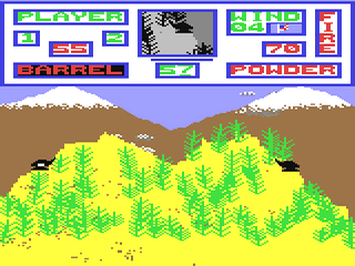
Artillery Duel was an early example of the genre, and appeared on such systems as the Bally Astrocade and Commodore 64 (pictured).
To pick just one artillery game is difficult since it’s a genre in its own right. Artillery simulations and games have been around for almost as long as computers, and most commonly see two players take turns to adjust the trajectory of their tank’s turret and fire a projectile at their opponent. The earliest versions for microcomputers appeared in the mid-seventies, and the genre continued to develop; increasingly complex scenarios appeared involving historical settings or, as we saw from the mid-90s on, even offbeat ideas like battles between factions of worms.
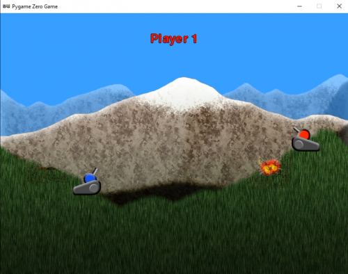
To code the basics of an artillery game, we’ll need two tanks with turrets, a landscape, and some code to work out who shot what, in which direction, and where said shot landed. Let’s start with the landscape. If we create a landscape in two parts – a backdrop and foreground – we can make the foreground destructible so that when a missile explodes it damages part of the landscape. This is a common effect used in artillery games, and sometimes makes the gameplay more complicated as the battle progresses. In our example, we have a grass foreground overlaid on a mountain scene. We then need a cannon for each player. In this case, we’ve used a two-part image, one for the base and one for the turret, which means the latter can be rotated using the up and down keys.
Our homage to the artillery game genre. Fire away at your opponent, and hope they don’t hit back first.
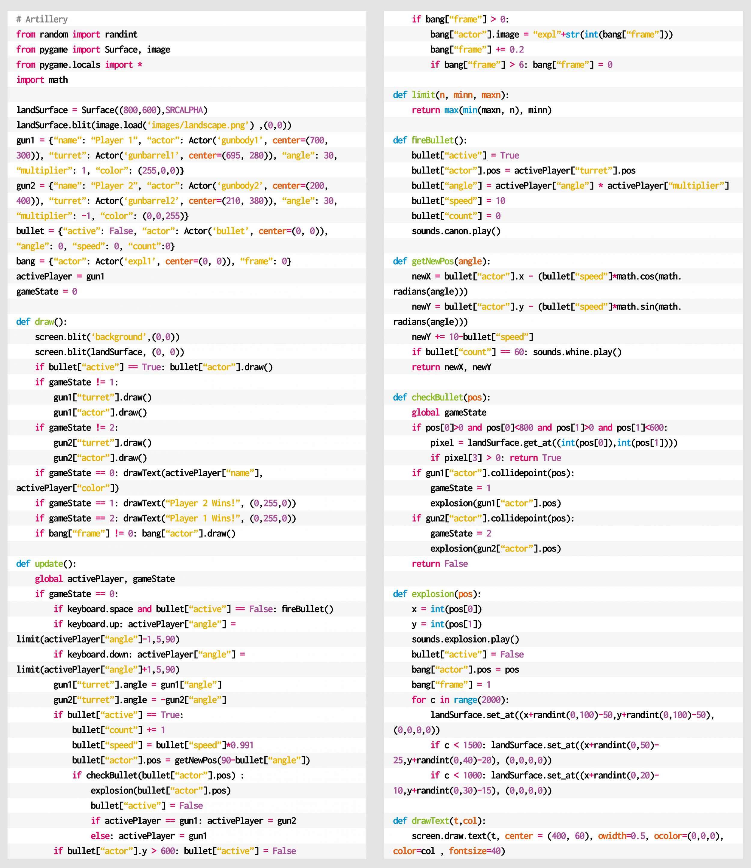
For this code example, we can use the Python dictionary to store several bits of data about the game objects, including the Actor objects. This makes the data handling tidy and is quite similar to the way that JSON is used in JavaScript. We can use this method for the two cannons, the projectile, and an explosion object. As this is a two-player game, we’ll alternate between the two guns, allowing the arrow keys to change the angle of the cannon. When the SPACE bar is pressed, we call the firing sequence, which places the projectile at the same position as the gun firing it. We then move the missile through the air, reducing the speed as it goes and allowing the effects of gravity to pull it towards the ground.
We can work out whether the bullet has hit anything with two checks. The first is to do a pixel check with the foreground. If this comes back as not transparent, then it has hit the ground, and we can start an explosion. To create a hole in the foreground, we can write transparent pixels randomly around the point of contact and then set off an explosion animation. If we test for a collision with a gun, we may find that the bullet has hit the other player and after blowing up the tank, the game ends. If the impact only hit the landscape, though, we can switch control over to the other player and let them have a go.
So that’s your basic artillery game. But rest assured there are plenty of things to add – for example, wind direction, power of the shot, variable damage depending on proximity, or making the tanks fall into holes left by the explosions. You could even change the guns into little wiggly creatures and make your own homage to Worms.
Here’s Mark’s code for an artillery-style tank game. To get it working on your system, you’ll need to install Pygame Zero. And to download the full code and assets, head here.
Get your copy of Wireframe issue 44
You can read more features like this one in Wireframe issue 44, available directly from Raspberry Pi Press — we deliver worldwide.
And if you’d like a handy digital version of the magazine, you can also download issue 44 for free in PDF format.
Wireframe #44, bringing the past and future of Worms to the fore.
Make sure to follow Wireframe on Twitter and Facebook for updates and exclusive offers and giveaways. Subscribe on the Wireframe website to save up to 72% compared to newsstand pricing!
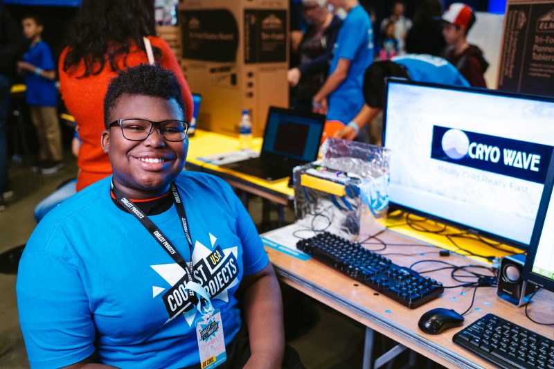
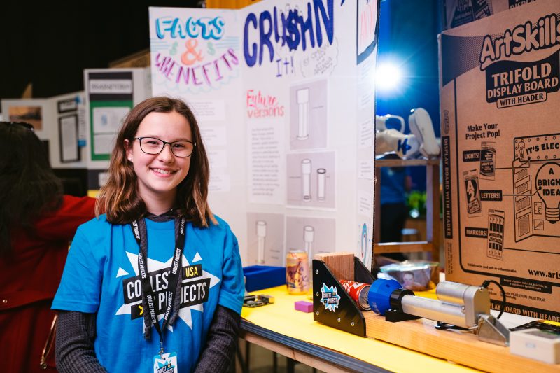
We’re proud to show our support for This is Engineering Day, an annual campaign from the Royal Academy of Engineering to bring engineering to life for young people by showcasing its variety and creativity. This year’s #BeTheDifference theme focuses on the positive impact engineering can have on everyday life and on the world we live in. So what better way for us to celebrate than to highlight our community’s young digital makers — future engineers — and their projects created for social good!
So many Coolest Projects participants present tech projects they’ve created for social good.
We’re also delighted to have special guest Dr Lucy Rogers on our This Is Engineering–themed Digital Making at Home live streamtoday at 5.30pm GMT, where she will share insights into her work as a creative inventor.
Your young people can ask inventor Dr Lucy Rogers their questions live today! Photo credit: Karla Gowlett
Future engineers creating projects for social good
In July, we were lucky enough to have Dr Hayaatun Sillem, CEO of the Royal Academy of Engineering (RAEng), as a judge for Coolest Projects, our technology fair for young creators. Dr Hayaatun Sillem says, “Engineering is a fantastic career if you want to make a difference, improve people’s lives, and shape the future.”
Our community’s young digital makers want to #BeTheDifference
In total, the young people taking part in Coolest Projects 2020 online presented 560 projects, of which over 300 projects were made specifically for social good. Here’s a small sample from some future engineers across the world:
“Our project is a virtual big eye doorman that detects if you wear a mask […] we chose this project because we like artificial intelligence and robotics and we wanted to help against the coronavirus.”
“I want people to put trash in the correct place so I made this AI trash can. This AI trash can separates the trash. I used ML2 Scratch. I used a camera to help the computer learn what type of trash it is.”
“As we know, burglary cases are very frequent and it is upsetting for the families whose houses are burglarised and [can] make them feel fearful, sad and helpless. Therefore, I tried to build a system which will help everyone to secure their houses.”
Tune in today: This is Engineering-themed live stream with special guest Dr Lucy Rogers
Professor Lucy Rogers PhD is an inventor with a sense of fun! She is a Fellow of the RAEng, and RAEng Visiting Professor of Engineering:Creativity and Communication at Brunel University, London. She’s also a Fellow of the Institution of Mechanical Engineers. Adept at bringing ideas to life, from robot dinosaurs to mini mannequins — and even a fartometer for IBM! — she has developed her creativity and communication skills and shares her tricks and tools with others.
Here Dr Lucy Rogers shares her advice for young people who want to get involved in engineering:
1. Create your own goal
A goal or a useful problem will help you get over the steep learning curve that is inevitable in learning about new pieces of technology. Your goal does not have to be big: my first Internet of Things project was making a LED shine when the International Space Station was overhead.
2. Make your world a little better
To me “engineering” is really “problem-solving”. Find problems to solve. You may have to make something, program something, or do something. How can you make your own world a little better?
3. Learn how to fail safely
Learn how to fail safely: break projects into smaller pieces, and try each piece. If it doesn’t work, you can try again. It’s only at the end of a project that you should put all the “working” pieces together (and even then, they may not work nicely together!)
Dr Lucy Rogers will be joining our Digital Making at Home educators on our This is Engineering-themed live stream today at 5.30pm GMT.
This is your young people’s chance to be inspired by this amazing inventor! And we will take live questions via YouTube, Facebook, Twitter, and Twitch, so make sure your young people are able to get Dr Lucy’s live answers to their own questions about digital making, creativity, and all things engineering!
Engineering at home, right now
To get inspired about engineering right now, your young people can follow along step by step with Electricity generation, our brand-new, free digital making project on the impact of non-renewable energy on our planet!
While coding this Scratch project, learners input real data about the type and amount of natural resources that countries across the world use to generate electricity, and they then compare the results using an animated data visualisation.
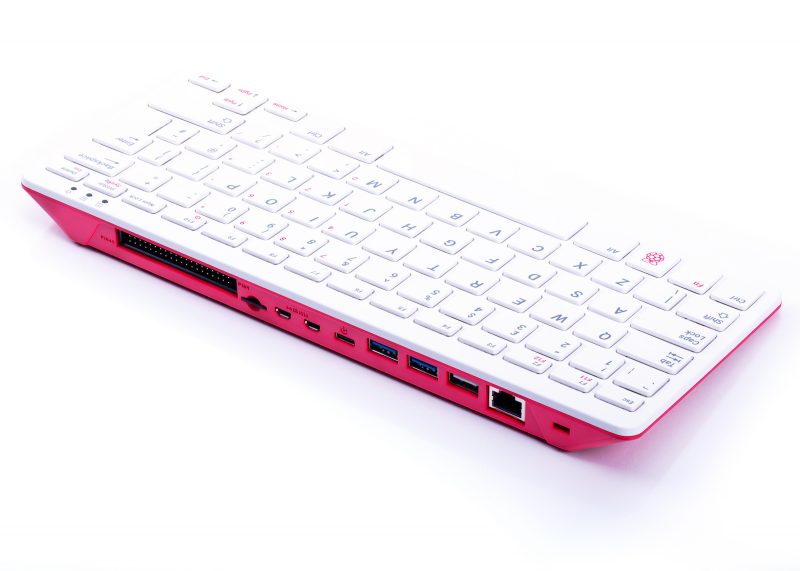
It’s been a journey, but it’s finally here, and I can talk about the secret Raspberry Pi 400 project! I’ll also try to cover some of the questions you asked following Eben’s announcement of Raspberry Pi 400 yesterday.
Four years in the making
It’s been over four years since the original idea of a Raspberry Pi inside a keyboard was discussed, before I even started working at Raspberry Pi Towers. Initially, the plan was for a kit with all the parts needed for people simply to open the box and get started by connecting the accessories to a “classic” credit-card sized Raspberry Pi. The challenge was that we needed a mouse and a keyboard: if we could manufacture a mouse and a keyboard, we could make a complete kit. How hard could it be? Then, within a day of our announcing our new keyboard and mouse, we saw a blog from someone who had milled out the keyboard and integrated a Raspberry Pi 3 Model A+ into it.
Our jaws dropped – we were impressed but we couldn’t say a word. Then others did the same with a Raspberry Pi Zero, and by that point we kind of expected that. We knew it was a good idea.
The keyboard and mouse were the big things we needed to sort out: once the quality control and supply chain were in place for those, we could move to fitting keyboard matrices to Raspberry Pi 400s, and achieve final assembly in Sony’s manufacturing facility in Wales. We had first planned to make a Raspberry Pi 3-based version, but it was clear that getting such a complex item into product wouldn’t happen until after we’d launched Raspberry Pi 4, and this would make the new product seem like a runner-up. So, instead, we started work on the Raspberry Pi 4-based version as soon as the design for that was finalised.
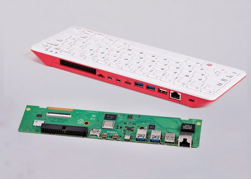
A fresh, new Raspberry Pi 4
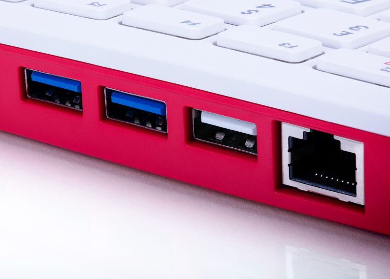
The board inside the housing is essentially a Raspberry Pi 4 unit, but with a fresh PCB design. It has the same USB and Ethernet system as the Raspberry Pi 4, but one of the USB2.0 ports is dedicated to the keyboard.
Left-handed?
We have already seen a few comments about the USB ports being on the left side of the unit, and the fact that this makes the mouse cable cross over for most right-handed users. The PCB shape had to be defined early on so that the industrial designers could get on with the housing design, and I then stared endlessly at the PCB layout, trying to get one of the USB ports to route to the right side without wrecking the signal integrity of the memory or the HDMI; I could not find a way to do this. Left-handed folks and Bluetooth mouse-owners will be happy at least!
Micro HDMI
Raspberry Pi 400 has dual-band 802.11b/g/n/ac wireless LAN and Bluetooth 5.0. Like Raspberry Pi 4, it has dual micro HDMI output which achieves up to 4K video. It would have been be lovely to have had full-size HDMI connectors, but in order to achieve this we would have to remove other functions, or make a bulkier unit. However, the kit does come with a micro HDMI-to-HDMI cable to cheer you all up.
We kept the GPIO connector since it is loved so much by beginners and experts alike, and this is after all a Raspberry Pi – we want people to be able to use it for tinkering and prototyping. The HAT functionality works better with an extender cable, which you can buy from numerous websites.
1.8GHz!
Raspberry Pi 400 has the same circuit layout of the power management, processor, and memory as Raspberry Pi 4, but with one major difference: we’ve adjusted the operating point to 1.8GHz! And did I mention cooling? We’ve solved the cooling challenge so users don’t have to give this any thought. Raspberry Pi 400 contains a heat spreader that dissipates the heat across the whole unit, front and back, so that no part of it will feel too hot to touch. In fact, there is enough thermal margin to overclock it, if you’re so inclined.
Why not the Compute Module?
Some folks have asked us why we did not fit the Raspberry Pi Compute Module inside. The reason is that above a certain scale, it generally makes more sense to go with a custom PCB rather than a module with a carrier board. With hundreds of thousands of Raspberry Pi 400 units in the first instance, we are above that scale.
Turn it off and on again
We also have a feature that is completely new to Raspberry Pi products: an on/off button! Power off is achieved by pressing Fn+F10. This is a soft control that negotiates with Linux to shut down, so you don’t corrupt your memory card or your USB drive. Power can be restored by holding down F10 (or Fn+F10) for two seconds.
Prototyping
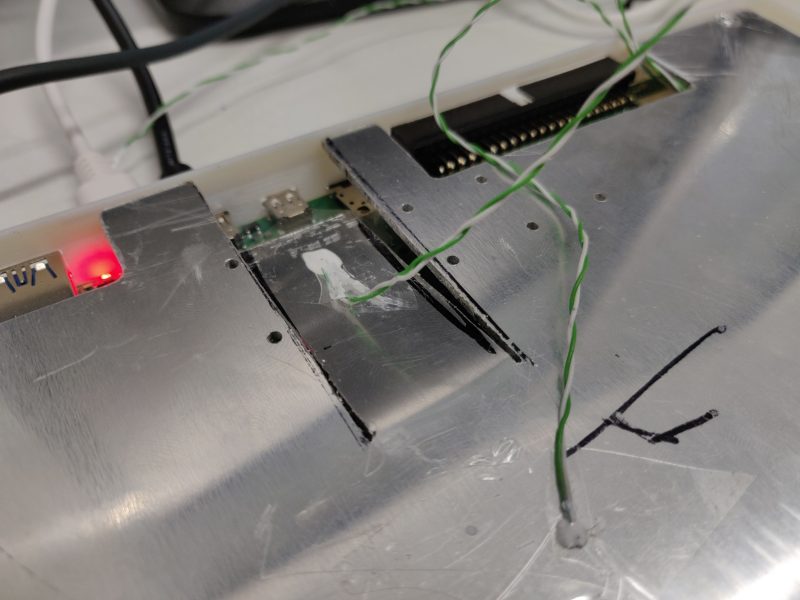
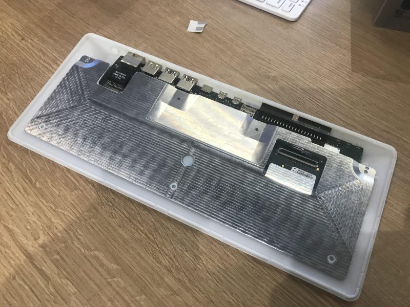
An early unit going through thermal analysis
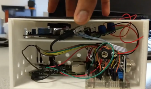
A lot of love went into making this the best possible product we can manufacture, and it has been through extensive alpha testing and compliance testing. I thought I would show you the insides of a very early prototype. There are already some teardown videos online if you want to see how Raspberry Pi 400 is put together; it has not changed much from this:
Inside one of the first Raspberry Pi 400 units – 3D-printed and CNC-machined. ~£1500 each to build!
Raspberry Pi 400 kit
The official Raspberry Pi mouse has been a lovely product to have available where Raspberry Pi 400 is concerned, because now we can provide a complete kit of official matching Raspberry Pi parts that looks fantastic on your desk. The kit comes with the SD card already programmed and inserted, so on Christmas day, you just need to plug it into the family TV and start coding. No frantic searches for somewhere that sells memory cards!
The kit includes:
Raspberry Pi 400 computer with choice of six keyboard countries (more to follow)
Official Raspberry Pi mouse
Raspberry Pi USB-C DC power source, with adaptors for each country
SD card ready-fitted in the unit with the latest software release installed
micro HDMI to HDMI cable
Jewel box to store the SD card
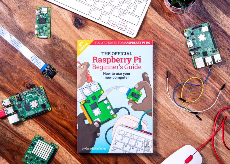
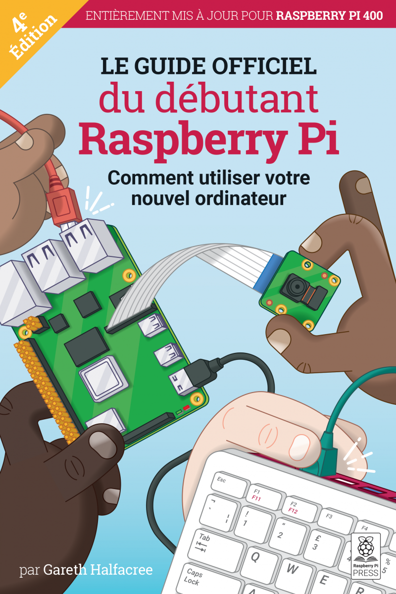
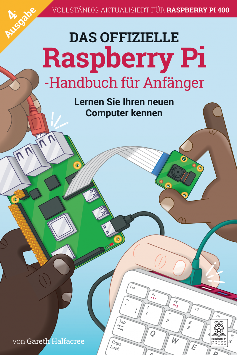
Fourth-edition Raspberry Pi Beginner’s Guide book with instructions for getting started with Raspberry Pi 400, as well as loads of things you can do with it
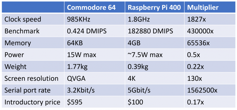
Ode to Commodore
Finally, a bit of fun to finish with. On Christmas morning 1985, I opened the polystyrene box of a Commodore 64 computer and the world switched on for me. It had the best games and the best sound, and it was easy to program. We think the combination of gaming and programming still works today, but we’ve come a long way since 1985. Here’s a chart to show how a Commodore 64 and a Raspberry Pi 400 compare.
I particularly like the benchmark increase for less than half the power. This makes Raspberry Pi 4 almost a million times more efficient at processing data.
We do hope this bring smiles to the faces of those fortunate enough to get one by Christmas. The factory has been running flat-out for the last two months building up stock – order yours soon though, since they’ll sell quickly!
Special thanks to…
Alwyn Roberts, Andy Liu, Anthony Morton, Antti Silventoinen, Austin Su, Ben Stephens, Brendan Moran, Craig Wightman, Daniel Thompsett, David Christie, David John, David Lenton, Dominic Plunkett, Eddie Thorn, Gordon Hollingworth, Helen Marie, Jack Willis, James Adams, Jeremy Wang, Joe Whaley, Keiran Abraham, Keri Norris, Kuanhsi Ho, Laurent Le Mentec, Mandy Oliver, Mark Evans, Michael Howells, Mike Buffham, Mike Unwin, Peter Challis, Phil Elwell, Rhys Polley, Richard Jones, Rob Matthews, Roger Thornton, Sherman Liu, Simon Lewis, Simon Oliver, Tim Gover, Tony Jones, Viktor Lundström, Wu Hairong, and all the alpha testers and resellers who made Raspberry Pi 400 possible.
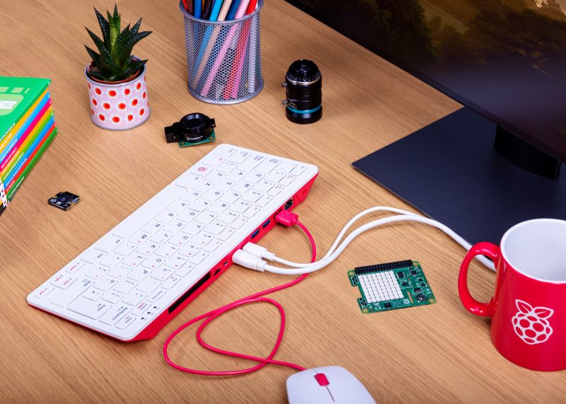
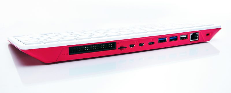
Raspberry Pi has always been a PC company. Inspired by the home computers of the 1980s, our mission is to put affordable, high-performance, programmable computers into the hands of people all over the world. And inspired by these classic PCs, here is Raspberry Pi 400: a complete personal computer, built into a compact keyboard.
https://youtu.be/ZSvHJ97d8n8
Raspberry Pi 4, which we launched in June last year, is roughly forty times as powerful as the original Raspberry Pi, and offers an experience that is indistinguishable from a legacy PC for the majority of users. Particularly since the start of the COVID-19 pandemic, we’ve seen a rapid increase in the use of Raspberry Pi 4 for home working and studying.
But user friendliness is about more than performance: it can also be about form factor. In particular, having fewer objects on your desk makes for a simpler set-up experience. Classic home computers – BBC Micros, ZX Spectrums, Commodore Amigas, and the rest – integrated the motherboard directly into the keyboard. No separate system unit and case; no keyboard cable. Just a computer, a power supply, a monitor cable, and (sometimes) a mouse.
Raspberry Pi 400
We’ve never been shy about borrowing a good idea. Which brings us to Raspberry Pi 400: it’s a faster, cooler 4GB Raspberry Pi 4, integrated into a compact keyboard. Priced at just $70 for the computer on its own, or $100 for a ready-to-go kit, if you’re looking for an affordable PC for day-to-day use this is the Raspberry Pi for you.
Buy the kit
The Raspberry Pi 400 Personal Computer Kit is the “Christmas morning” product, with the best possible out-of-box experience: a complete PC which plugs into your TV or monitor. The kit comprises:
A Raspberry Pi 400 computer
Our official USB mouse
Our official USB-C power supply
An SD card with Raspberry Pi OS pre-installed
A micro HDMI to HDMI cable
The official Raspberry Pi Beginner’s Guide
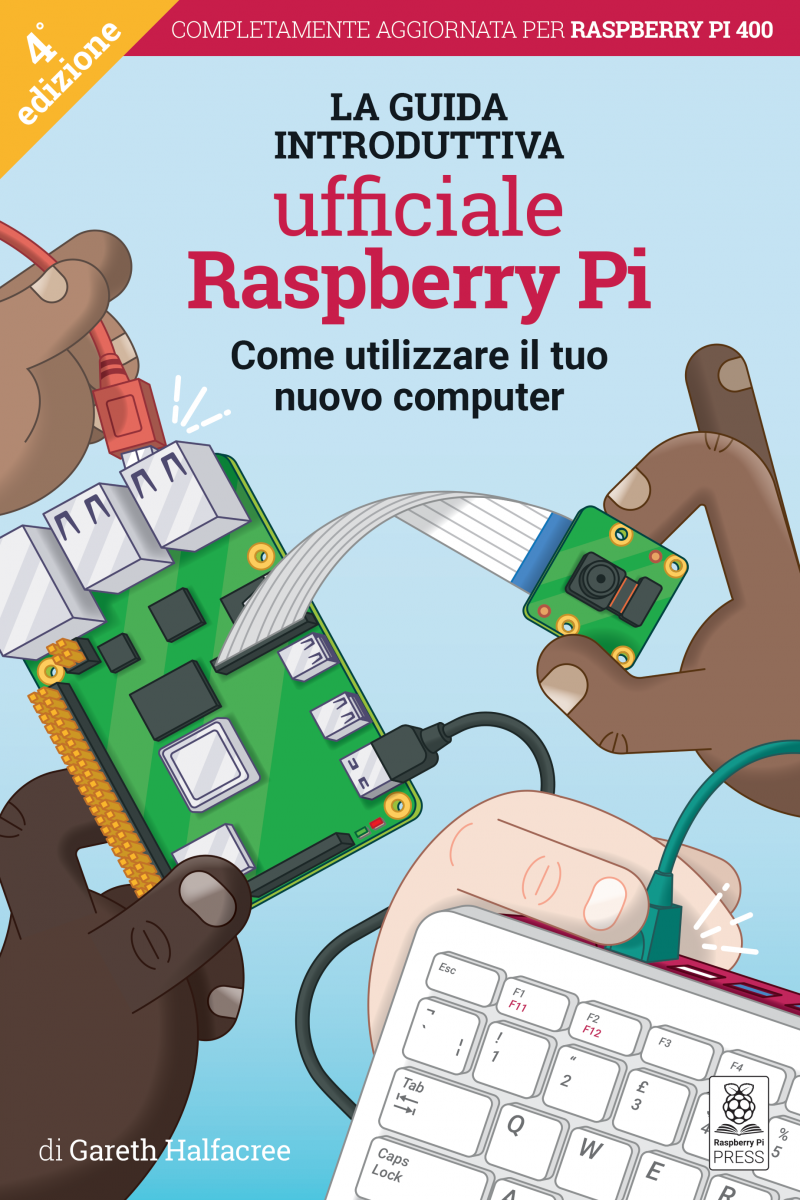
At launch, we are supporting English (UK and US), French, Italian, German, and Spanish keyboard layouts, with (for the first time) translated versions of the Beginner’s Guide. In the near future, we plan to support the same set of languages as our official keyboard.
Buy the computer
Saving money by bringing your own peripherals has always been part of the Raspberry Pi ethos. If you already have the other bits of the kit, you can buy a Raspberry Pi 400 computer on its own for just $70.
Buy the book
To accompany Raspberry Pi 400, we’ve released a fourth edition of our popular Raspberry Pi Beginner’s Guide, packed with updated material to help you get the most out of your new PC.
You can buy a copy of the Beginner’s Guide today from the Raspberry Pi Press store, or download a free PDF.
Where to buy Raspberry Pi 400
UK, US, and French Raspberry Pi 400 kits and computers are available to buy right now. Italian, German, and Spanish units are on their way to Raspberry Pi Approved Resellers, who should have them in stock in the next week.
We expect that Approved Resellers in India, Australia, and New Zealand will have kits and computers in stock by the end of the year. We’re rapidly rolling out compliance certification for other territories too, so that Raspberry Pi 400 will be available around the world in the first few months of 2021.
Of course, if you’re anywhere near Cambridge, you can head over to the Raspberry Pi Store to pick up your Raspberry Pi 400 today.
What does everyone else think?
We let a handful of people take an early look at Raspberry Pi 400 so they could try it out and pull together their thoughts to share with you. Here’s what some of them made of it.
Simon Martin, who has spent the last couple of years bringing Raspberry Pi 400 to life, will be here tomorrow to share some of the interesting technical challenges that he encountered along the way. In the meantime, start thinking about what you’ll do with your Raspberry Pi PC.
How do you create a 3D model of a historic graveyard? With eight Raspberry Pi computers, as Rob Zwetsloot discovers in the latest issue of The MagPi magazine, out now.
The software builds up the 3D model of the graveyard
“In the city centre of Dundee is a historical burial ground, The Howff,” says Daniel Muirhead. We should probably clarify that he’s a 3D artist. “This old graveyard is densely packed with around 1500 gravestones and other funerary monuments, which happens to make it an excellent technical challenge for photogrammetry photo capture.”
This architecture, stone paths, and vibrant flora is why Daniel ended up creating a 3D-scanning rig out of eight Raspberry Pi computers. And the results are quite stunning.
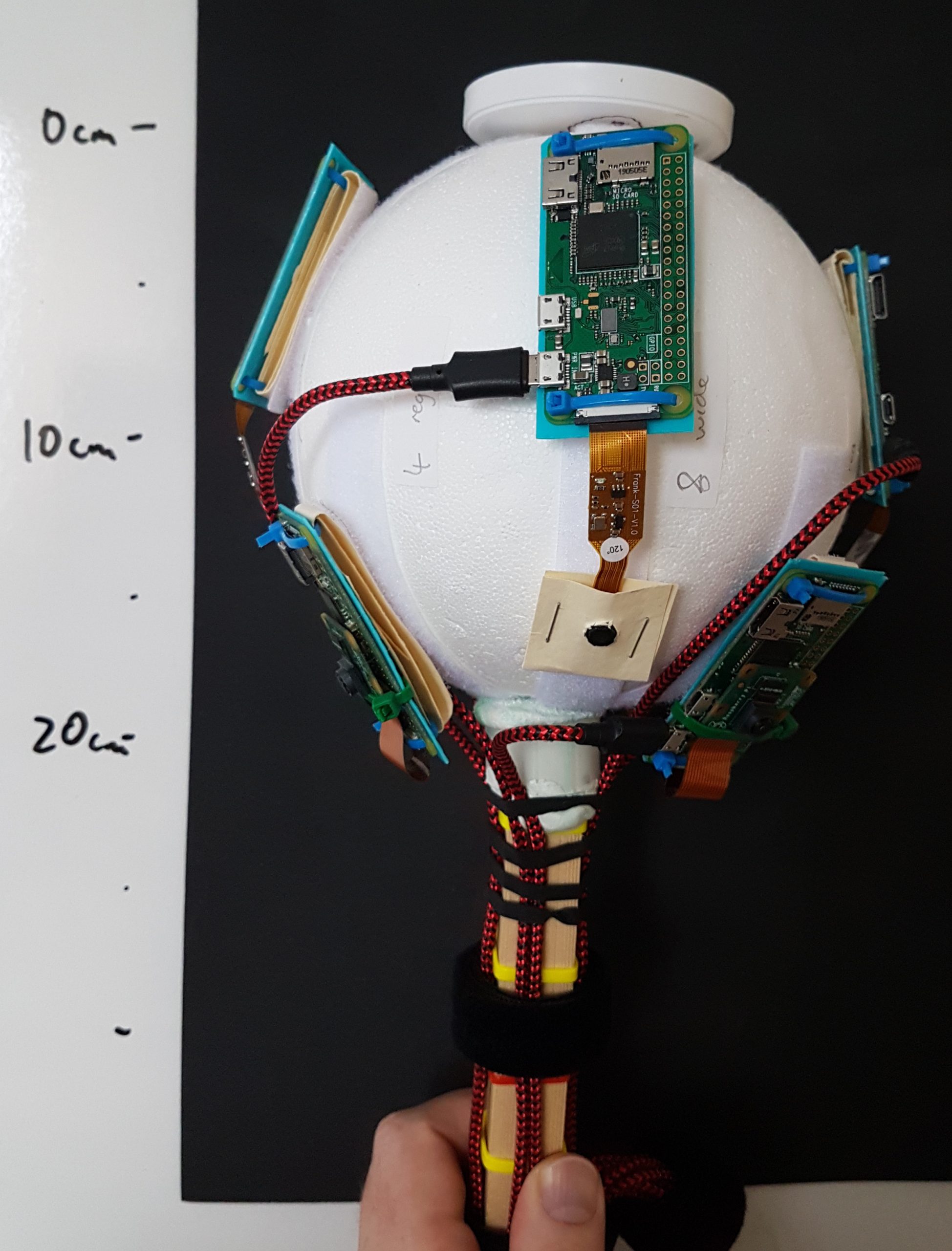
Eight Raspberry Pi computers are mounted to the ball, with cameras pointing towards the ground
“The goal of this project was to capture photos for use in generating a 3D model of the ground,” he continues. “That model will be used as a base for attaching individual gravestone models and eventually building up a full composite model of this complex subject. The ground model will also be purposed for rendering an ultra-high-resolution map of the graveyard. The historical graveyard has a very active community group that are engaged in its study and digitisation, the Dundee Howff Conservation Group, so I will be sharing my digital outputs with them.”
Google graveyard
There are thousands of pictures, like this one, being used to create the model
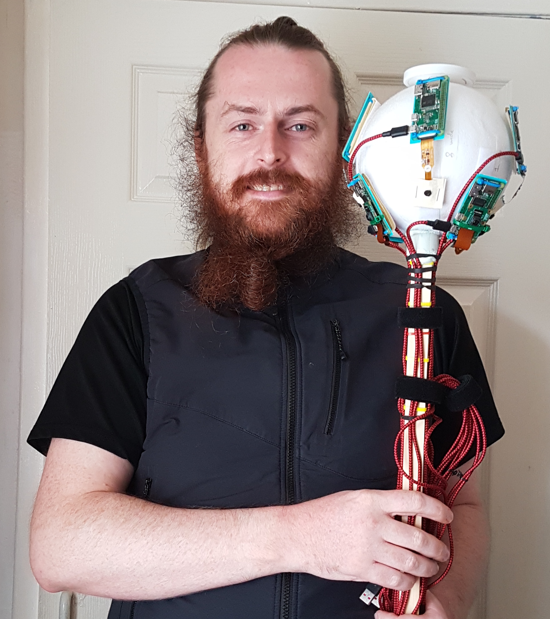
To move the rig throughout the graveyard, Daniel used himself as the major moving part. With the eight Raspberry Pi cameras taking a photo every two seconds, he was able to capture over 180,000 photos over 13 hours of capture sessions.
“The rig was held above my head and the cameras were angled in such a way as to occlude me from view, so I was not captured in the photographs which instead were focused on the ground,” he explains. “Of the eight cameras, four were the regular model with 53.5 ° horizontal field of view (FoV), and the other four were a wide-angle model with 120 ° FoV. These were arranged on the rig pointing outwards in eight different directions, alternating regular and wide-angle, all angled at a similar pitch down towards the ground. During capture, the rig was rotated by +45 ° for every second position, so that the wide-angles were facing where the regulars had been facing on the previous capture, and vice versa.” Daniel worked according to a very specific grid pattern, staying in one spot for five seconds at a time, with the hopes that at the end he’d have every patch of ground photographed from 16 different positions and angles.
Maker Daniel Muirhead is a 3D artist with an interest in historical architecture
“With a lot of photo data to scan through for something fairly complex, we wondered how well the system had worked. Daniel tells us the only problems he had were with some bug fixing on his code: “The images were separated into batches of around 10,000 (1250 photos from each of the eight cameras), plugged into the photogrammetry software, and the software had no problem in reconstructing the ground as a 3D model.”
Accessible 3D surveying
He’s now working towards making it accessible and low-cost to others that might want it. “Low-cost in the triple sense of financial, labour, and time,” he clarifies. “I have logged around 8000 hours in a variety of photogrammetry softwares, in the process capturing over 300,000 photos with a regular camera for use in such files, so I have some experience in this area.”
“With the current state of technology, it should be possible with around £1000 in equipment to perform a terrestrial photo-survey of a town centre in under an hour, then with a combined total of maybe three hours’ manual processing and 20 hours’ automated computer processing, generate a high-quality 3D model, the total production time being under 24 hours. It should be entirely plausible for a local community group to use such a method to perform weekly (or at least monthly) 3D snapshots of their town centre.”
We love seeing how quickly our community of makers responds when we drop a new product, and one of the fastest off the starting block when we released the new Raspberry Pi Compute Module 4 on Monday was YouTuber Jeff Geerling.
Jeff Geerling
We made him keep it a secret until launch day after we snuck one to him early so we could see what one of YouTube’s chief advocates for our Compute Module line thought of our newest baby.
So how does our newest board compare to its predecessor, Compute Module 3+? In Jeff’s first video (above) he reviews some of Compute Module 4’s new features, and he has gone into tons more detail in this blog post.
Jeff also took to live stream for a Q&A (above) covering some of the most asked questions about Compute Module 4, and sharing some more features he missed in his initial review video.
His next video (above) is pretty cool. Jeff explains:
“Everyone knows you can overclock the Pi 4. But what happens when you overclock a Compute Module 4? The results surprised me!”
Jeff Geerling
And again, there’s tons more detail on temperature measurement, storage performance, and more on Jeff’s blog.
Top job, Jeff. We have our eyes on your channel for more videos on Compute Module 4, coming soon.
Explore our new free pathway of environmental digital making projects for young people! These new step-by-step projects teach learners Scratch coding and include real-world data — from data about the impact of deforestation on wildlife to sea turtle tracking information.
By following along with the digital making projects online, young people will discover how they can use technology to protect our planet, all while improving their computing skills.
One of the new projects is an automatic creature counter based on colour recognition with Scratch
The projects help young people affect change
In the projects, learners are introduced to 5 of the United Nations’ 17 Sustainable Development Goals (SDGs) with an environment focus:
Affordable and Clean Energy
Responsible Consumption and Production
Climate Action
Life Below Water
Life on Land
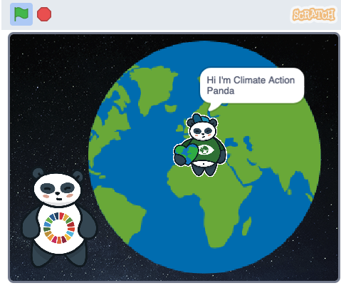
The first project in the new pathway is an animation about the UN’s five SDGs focused on the environment.
Technology, science, maths, geography, and design all play a part in the projects. Following along with the digital making projects, young people learn coding and computing skills while drawing on a range of data from across the world. In this way they will discover how computing can be harnessed to collect environmental data, to explore causes of environmental degradation, to see how humans influence the environment, and ultimately to mitigate negative effects.
Where does the real-world data come from?
To help us develop these environmental digital making projects, we reached out to a number of organisations with green credentials:
We asked the team behind the Ecosia search engine, profits from which get invested in sustainability projects, for their guidance on growing trees. You can watch Ecosia software engineer Jessica Greene chat to us on our weekly Digital Making at Home live stream for young people.
We collaborated with the Shuttleworth Foundation who have developed inexpensive electronic tags that can be safely attached to real sea turtles to track their movement. You can watch Alasdair Davies, who is part of this wildlife project, chat to us on another round of our Digital Making at Home live stream for young people.
A sea turtle is being tagged so its movements can be tracked
Inspiring young people about coding with real-world data
The digital making projects, created with 9- to 11-year-old learners in mind, support young people on a step-by-step pathway to develop their skills gradually. Using the block-based visual programming language Scratch, learners build on programming foundations such as sequencing, loops, variables, and selection. The project pathway is designed so that learners can apply what they learned in earlier projects when following along with later projects!
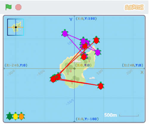
The final project in the pathway, ‘Turtle tracker’, uses real-world data of migrating sea turtles!
We’re really excited to help learners explore the relationship between technology and the environment with these new digital making projects. Connecting their learning to real-world scenarios not only allows young people to build their knowledge of computing, but also gives them the opportunity to affect change and make a difference to their world!
Discover the new digital making projects yourself!
With Green goals, learners create an animation to present the United Nations’ environment-focused Sustainable Development Goals.
Through Save the shark, young people explore sharks’ favourite food source (fish, not humans!), as well as the impact of plastic in the sea, which harms sharks in their natural ocean habitat.
With the Tree life simulator project guide, learners create a project that shows the impact of land management and deforestation on trees, wildlife, and the environment.
Computers can be used to study wildlife in areas where it’s not practical to do so in person. In Count the creatures, learners create a wildlife camera using their computer’s camera and Scratch’s new video sensing extension!
Electricity is important. After all, it powers the computer that learners are using! In Electricity generation, learners input real data about the type and amount of natural resources countries across the world use to generate electricity, and they then compare the results using an animated data visualisation.
Understanding the movements of endangered turtles helps to protect these wonderful animals. In this new Turtle tracker project, learners use tracking data from real-life turtles to map their movements off the coast of West Africa.
Code along wherever you are!
All of our projects are free to access online at any time and include step-by-step instructions. They can be undertaken in a club, classroom, or at home. Young people can share the project they create with their peers, friends, family, and the wider Scratch community.
Visit the Protect our planet pathway to experience the projects yourself.
In the latest issue of HackSpace Magazine, out now, @MrPJEvans shows you how to add voice commands to your projects with a Raspberry Pi 4 and a microphone.
It’s amazing how we’ve come from everything being keyboard-based to so much voice control in our lives. Siri, Alexa, and Cortana are everywhere and happy to answer questions, play you music, or help automate your household.
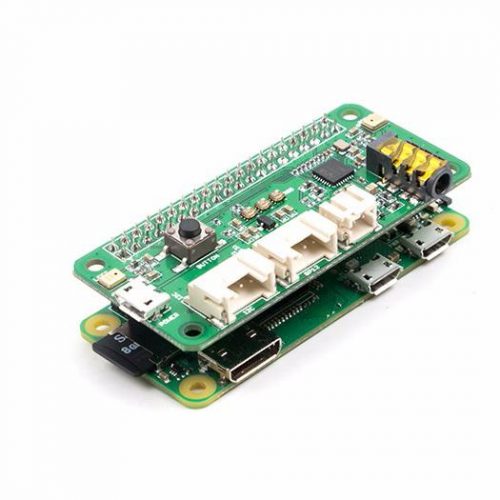
For the keen maker, these offerings may not be ideal for augmenting their latest project as they are closed systems. The good news is, with a bit of help from Google, you can add voice recognition to your project and have complete control over what happens. You just need a Raspberry Pi 4, a speaker array, and a Google account to get started.
Set up your microphone
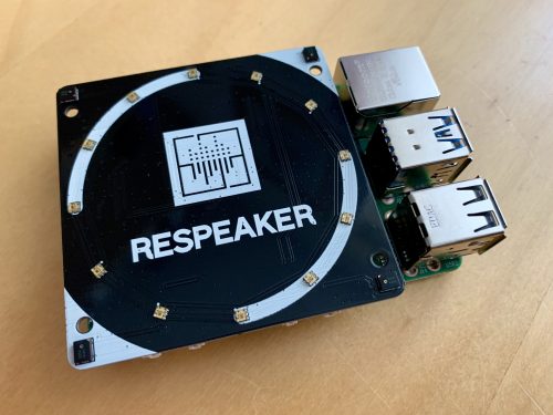
This clever speaker uses four microphones working together to increase accuracy. A ring of twelve RGB LEDs can be coded to react to events, just like an Amazon Echo
For a home assistant device, being able to hear you clearly is an essential. Many microphones are either too low-quality for the task, or are unidirectional: they only hear well in one direction. To the rescue comes Seeed’s ReSpeaker, an array of four microphones with some clever digital processing to provide the kind of listening capability normally found on an Amazon Echo device or Google Assistant. It’s also in a convenient HAT form factor, and comes with a ring of twelve RGB LEDs, so you can add visual effects too. Start with a Raspberry Pi OS Lite installation, and follow these instructions to get your ReSpeaker ready for use.
Install Snowboy
You’ll see later on that we can add the power of Google’s speech-to-text API by streaming audio over the internet. However, we don’t want to be doing that all the time. Snowboy is an offline ‘hotword’ detector. We can have Snowboy running all the time, and when your choice of word is ‘heard’, we switch to Google’s system for accurate processing. Snowboy can only handle a few words, so we only use it for the ‘trigger’ words. It’s not the friendliest of installations so, to get you up and running, we’ve provided step-by-step instructions.
There’s also a two-microphone ReSpeaker for the Raspberry Pi Zero
Create your own hotword
As we’ve just mentioned, we can have a hotword (or trigger word) to activate full speech recognition so we can stay offline. To do this, Snowboy must be trained to understand the word chosen. The code that describes the word (and specifically your pronunciation of it) is called the model. Luckily, this whole process is handled for you at snowboy.kitt.ai, where you can create a model file in a matter of minutes and download it. Just say your choice of words three times, and you’re done. Transfer the model to your Raspberry Pi 4 and place it in your home directory.
Let’s go Google
ReSpeaker can use its multiple mics to detect distance and direction
After the trigger word is heard, we want Google’s fleet of super-servers to help us transcribe what is being said. To use Google’s speech-to-text API, you will need to create a Google application and give it permissions to use the API. When you create the application, you will be given the opportunity to download ‘credentials’ (a small text file) which will allow your setup to use the Google API. Please note that you will need a billable account for this, although you get one hour of free speech-to-text per month. Full instructions on how to get set up can be found here.
Install the SDK and transcriber
To use Google’s API, we need to install the firm’s speech-to-text SDK for Python so we can stream audio and get the results. On the command line, run the following:pip3 install google-cloud-speech (If you get an error, run sudo apt install python3-pip then try again). Remember that credentials file? We need to tell the SDK where it is: export GOOGLE_APPLICATION_CREDENTIALS="/home/pi/[FILE_NAME].json" (Don’t forget to replace [FILE_NAME] with the actual name of the JSON file.) Now download and run this test file. Try saying something and see what happens!
Putting it all together
Now we can talk to our Raspberry Pi, it’s time to link the hotword system to the Google transcription service to create our very own virtual assistant. We’ve provided sample code so that you can see these two systems running together. Run it, then say your chosen hotword. Now ask ‘what time is it?’ to get a response. (Don’t forget to connect a speaker to the audio output if you’re not using HDMI.) Now it’s over to you. Try adding code to respond to certain commands such as ‘turn the light on’, or ‘what time is it?’
Get HackSpace magazine 36 Out Now!
Each month, HackSpace magazine brings you the best projects, tips, tricks and tutorials from the makersphere. You can get it from the Raspberry Pi Press online store, The Raspberry Pi store in Cambridge, or your local newsagents.
Every year, we support the PA Raspberry Pi Competition for UK schools, run by PA Consulting. In this free competition, teams of students from schools all over the UK imagine, design, and create Raspberry Pi–powered inventions.
The PA Raspberry Pi Competition aims to inspire young people aged 8 to 18 to learn STEM skills, teamwork, and creativity, and to move toward a career in STEM.
We invite all UK teachers to register if you have students at your school who would love to take part!
Among all the entries, judges from the tech sector and the Raspberry Pi Foundation choose the finalists with the most outstanding inventions in their age group.
The final teams get to take part in an exciting awards event to present their creations so that the final winners can be selected. This round’s PA Raspberry Pi Awards Ceremony takes place on Wednesday 28 April 2021, and PA Consulting are currently considering whether this will be a physical or virtual event.
All teams that participate in the competition will be rewarded with certificates, and there’s of course the chance to win trophies and prizes too!
You can prepare with our free online courses
If you would like to boost your skills so you can better support your team, then sign up to one of our free online courses designed for educators:
A look inside the air quality-monitoring project by Team Tempest, last round’s winners in the Y7–9 group
Find out more at the PA Raspberry Pi Competition webinar!
To support teachers in guiding their teams through the competition, PA Consulting will hold a webinar on 12 November 2020 at 4.30–5.30pm. Sign up to hear first-hand what’s involved in taking part in the PA Raspberry Pi Competition, and use the opportunity to ask questions!
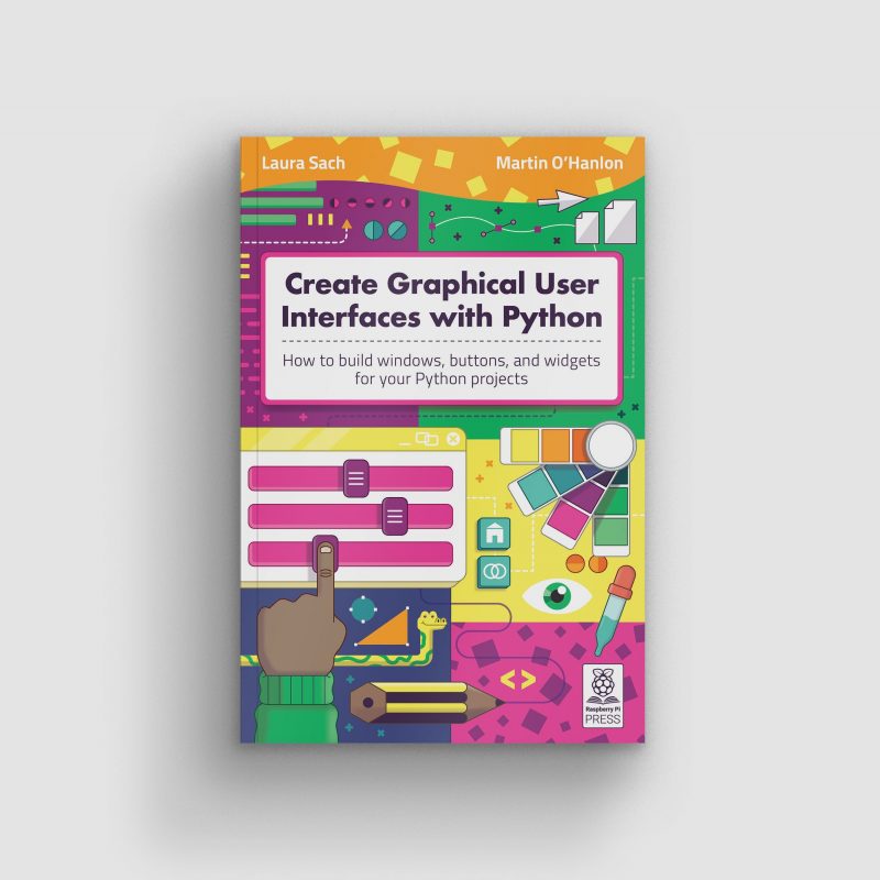
Laura Sach and Martin O’Hanlon, who are both Learning Managers at the Raspberry Pi Foundation, have written a brand-new book to help you to get more out of your Python projects.
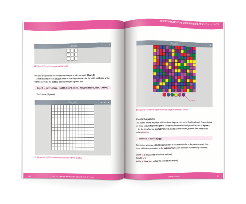
In Create Graphical User Interfaces with Python, Laura and Martin show you how to add buttons, boxes, pictures, colours, and more to your Python programs using the guizero library, which is easy to use and accessible for all, no matter your Python skills.
This new 156-page book is suitable for everyone — from beginners to experienced Python programmers — who wants to explore graphical user interfaces (GUIs).
Meet the authors
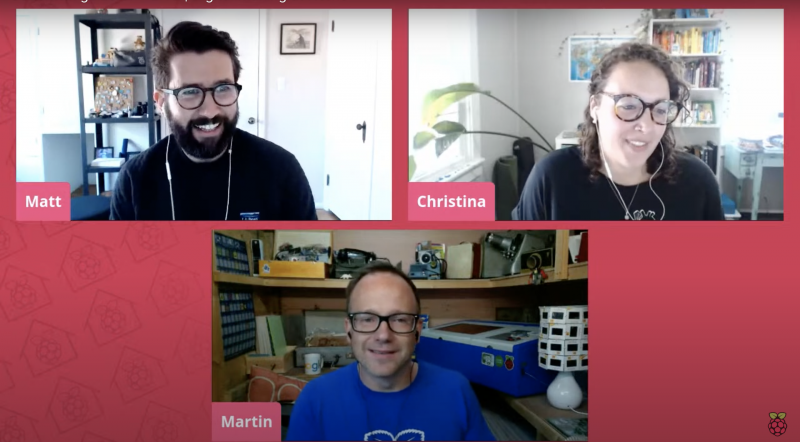
That’s Martin in the blue T-shirt with our Digital Making at Home live stream hosts Matt and Christina
Laura is also pretty cool! Here she is showing you how to solder your Raspberry Pi header pins:
Hi Laura!
Martin and Laura are also tonnes of fun on Twitter. You can find Martin as @martinohanlon, and Laura goes by @codeboom.
10 fun projects
In Create Graphical User Interfaces with Python, you’ll find ten fun Python projects to create with guizero, including a painting program, an emoji match game, and a stop-motion animation creator.
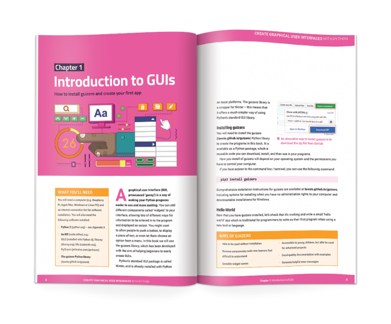
A peek inside Laura’s and Martin’s new book
You will also learn:
How to create fun Python games and programs
How to code your own graphical user interfaces using windows, text boxes, buttons, images, and more
And if you don’t need the lovely new book, with its new-book smell, in your hands in real life, you can download a PDF version for free, courtesy of The MagPi magazine.
In computing education research, considerable focus has been put on the design of teaching materials and learning resources, and investigating how young people learn computing concepts. But there has been less focus on assessment, particularly assessment for learning, which is called formative assessment. As classroom teachers are engaged in assessment activities all the time, it’s pretty strange that researchers in the area of computing and computer science in school have not put a lot of focus on this.
That’s why in our most recent seminar, we were delighted to hear about formative assessment — assessment for learning — from Dr Shuchi Grover, of Looking Glass Ventures and Stanford University in the USA. Shuchi has a long track record of work in the learning sciences (called education research in the UK), and her contribution in the area of computational thinking has been hugely influential and widely drawn on in subsequent research.
Two types of assessment
Assessment is typically divided into two types:
Summative assessment (i.e. assessing what has been learned), which typically takes place through examinations, final coursework, projects, etcetera.
Formative assessment (i.e. assessment for learning), which is not aimed at giving grades and typically takes place through questioning, observation, plenary classroom activities, and dialogue with students.
Through formative assessment, teachers seek to find out where students are at, in order to use that information both to direct their preparation for the next teaching activities and to give students useful feedback to help them progress. Formative assessment can be used to surface misconceptions (or alternate conceptions) and for diagnosis of student difficulties.
Click to enlarge
As Shuchi outlined in her talk, a variety of activities can be used for formative assessment, for example:
Self- and peer-assessment activities (commonly used in schools).
Different forms of questioning and quizzes to support learning (not graded tests).
Rubrics and self-explanations (for assessing projects).
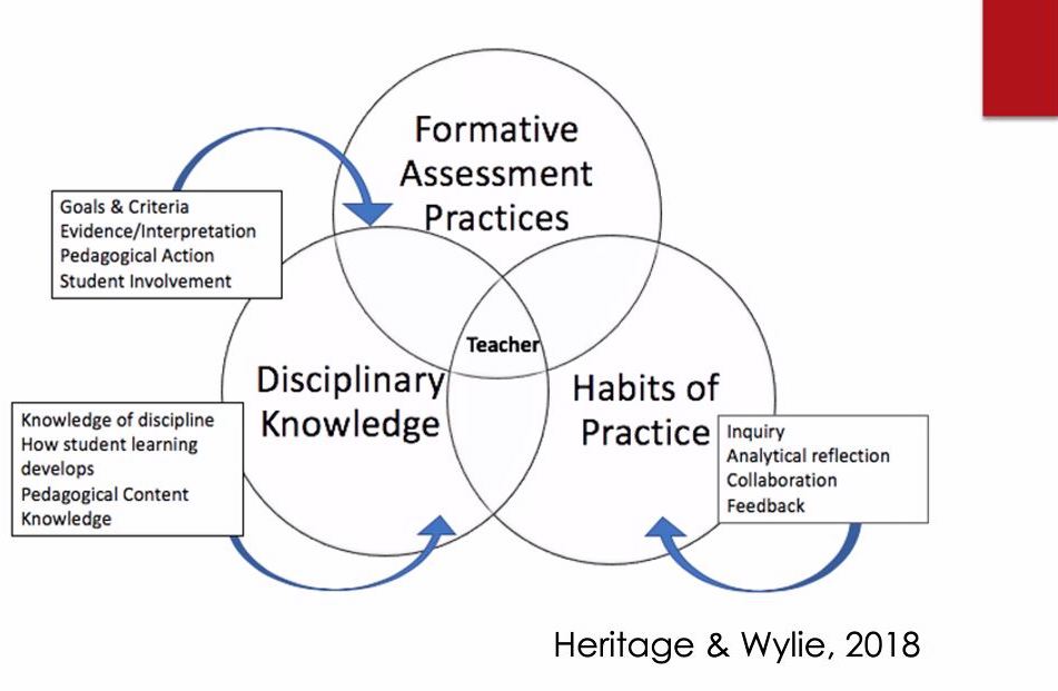
A framework for formative assessment
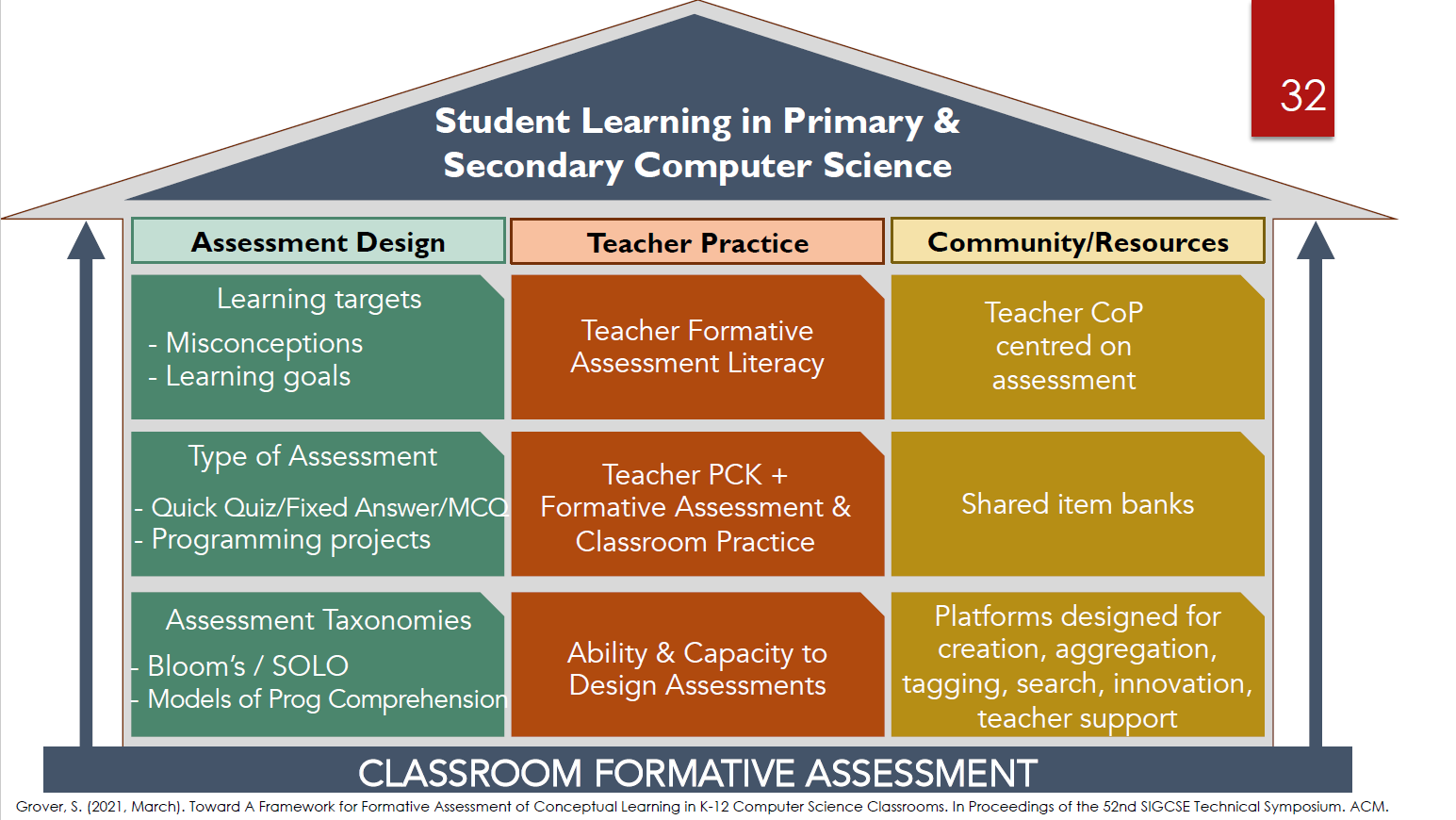
Shuchi described her own research in this topic, including a framework she has developed for formative assessment. This comprises three pillars:
Assessment design.
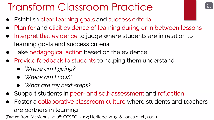
Teacher or classroom practice.
The role of the community in furthering assessment practice.
Click to enlarge
Shuchi’s presentation then focused on part of the first pillar in the framework: types of assessments, and particularly types of multiple-choice questions that can be automatically marked or graded using software tools. Tools obviously don’t replace teachers, but they can be really useful for providing timely and short-turnaround feedback for students.
As part of formative assessment, carefully chosen questions can also be used to reveal students’ misconceptions about the subject matter — these are called diagnostic questions. Shuchi discussed how in a classroom setting, teachers can employ this kind of question to help them decide what to focus on in future lessons, and to understand their students’ alternate or different conceptions of a topic.
Formative assessment of programming skills
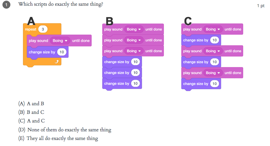
The remainder of the seminar focused on the formative assessment of programming skills. There are many ways of assessing developing programming skills (see Shuchi’s slides), including Parsons problems, microworlds, hotspot items, rubrics (for artifacts), and multiple-choice questions. As an MCQ example, in the figure below you can see some snippets of block-based code, which students need to read and work out what the outcome of running the snippets will be.
Click to enlarge
Questions such as this highlight that it’s important for learners to engage in code comprehension and code reading activities when learning to program. This really underlines the fact that such assessment exercises can be used to support learning just as much as to monitor progress.
Formative assessment: our support for teachers
Interestingly, Shuchi commented that in her experience, teachers in the UK are more used to using code reading activities than US teachers. This may be because code comprehension activities are embedded into the curriculum materials and support for pedagogy, both of which the Raspberry Pi Foundation developed as part of the National Centre for Computing Education in England. We explicitly share approaches to teaching programming that incorporate code reading, for example the PRIMM approach. Moreover, our work in the Raspberry Pi Foundation includes the Isaac Computer Science online learning platform for A level computer science students and teachers, which is centered around different types of questions designed as tools for learning.
All these materials are freely available to teachers wherever they are based.
Further work on formative assessment
Based on her work in US classrooms researching this topic, Shuchi’s call to action for teachers was to pay attention to formative assessment in computer science classrooms and to investigate what useful tools can support them to give feedback to students about their learning.
Click to enlarge
Shuchi is currently involved in an NSF-funded research project called CS Assess to further develop formative assessment in computer science via a community of educators. For further reading, there are two chapters related to formative assessment in computer science classrooms in the recently published book Computer Science in K-12 edited by Shuchi.
There was much to take away from this seminar, and we are really grateful to Shuchi for her input and look forward to hearing more about her developing project.
Join our next seminar
If you missed the seminar, you can find the presentation slides and a recording of the Shuchi’s talk on our seminars page.
In our next seminar on Tuesday 3 November at 17:00–18:30 BST / 12:00–13:30 EDT / 9:00–10:30 PT / 18:00–19:30 CEST, I will be presenting my work on PRIMM, particularly focusing on language and talk in programming lessons. To join, simply sign up with your name and email address.
Once you’ve signed up, we’ll email you the seminar meeting link and instructions for joining. If you attended this past seminar, the link remains the same.
I am delighted to share the news that we have appointed a new Chair and Trustees of the Raspberry Pi Foundation. Between them, they bring an enormous range of experience and expertise to what is already a fantastic Board of Trustees, and I am really looking forward to working with them.
John Lazar
Amali de Alwis
Charles Leadbeater
Dan Labbad
New Chair of the Board of Trustees: John Lazar
John Lazar has been appointed as the new Chair of the Board of Trustees. John is a software engineer and business leader who is focused on combining technology and entrepreneurship to generate lasting positive impact.
Formerly the Chairman and CEO of Metaswitch Networks, John is now an angel investor, startup mentor, non-executive chairman and board director, including serving as the Chair of What3Words. He is a Fellow of the Royal Academy of Engineering and played an active role in developing the programme of study for England’s school Computer Science curriculum. John has also spent many years working on tech-related non-profit initiatives in Africa and co-founded Enza Capital, which invests in early-stage African technology companies that solve pressing problems.
John takes over the Chair from David Cleevely, who has reached the end of his two three-year terms as Trustee and Chair of the Foundation. David has made a huge contribution to the Foundation over that time, and we are delighted that he will continue to be involved in our work as one of the founding members of the Supporters Club.
New Trustees: Amali de Alwis, Charles Leadbeater, Dan Labbad
Alongside John, we are welcoming three new Trustees to the Board of Trustees:
Amali de Alwis is the UK Managing Director of Microsoft for Startups, and is the former CEO of Code First: Girls. She is also a Board member at Ada National College for Digital Skills, sits on the Diversity & Inclusion Board at the Institute of Coding, is an Advisory Board member at the Founders Academy, and was a founding member at Tech Talent Charter.
Charles Leadbeater is an independent author, a social entrepreneur, and a leading authority on innovation and creativity. He has advised companies, cities, and governments around the world on innovation strategy and has researched and written extensively on innovation in education. Charles is also a Trustee of the Paul Hamlyn Foundation.
Dan Labbad is Chief Executive and Executive Member of the Board of The Crown Estate. He was previously at Lendlease, where he was Chief Executive Officer of Europe from 2009. Dan is also a Director of The Hornery Institute and Ark Schools.
New Member: Suranga Chandratillake
I am also delighted to announce that we have appointed Suranga Chandratillake as a Member of the Raspberry Pi Foundation. Suranga is a technologist, entrepreneur, and investor.
He founded the intelligent search company blinkx and is now a General Partner at Balderton Capital. Suranga is a Fellow of the Royal Academy of Engineering and a World Economic Forum Young Global Leader, and he serves on the UK Government’s Council for Science and Technology.
What is a Board of Trustees anyway?
As a charity, the Raspberry Pi Foundation is governed by a Board of Trustees who is ultimately responsible for what we do and how we are run. It is the Trustees’ job to make sure that we are focused on our mission, which for us means helping more people learn about computing, computer science, and related subjects. The Trustees also have all the usual responsibilities of company directors, including making sure that we use our resources effectively. As Chief Executive, I am accountable to the Board of Trustees.
We’ve always been fortunate to attract the most amazing people to serve as Trustees and, as volunteers, they are incredibly generous with their time, sharing their expertise and experience on a wide range of issues. They are an important part of the team. Trustees serve for up to two terms of three years so that we always have fresh views and experience to draw on.
How do you appoint Trustees?
Appointments to the Board of Trustees follow open recruitment and selection processes that are overseen by the Foundation’s Nominations Committee, supported by independent external advisers. Our aim is to appoint Trustees who bring different backgrounds, perspectives, and lived experience, as well as a range of skills. As with all appointments, we consider diversity at every aspect of the recruitment and selection processes.
Formally, Trustees are elected by the Foundation’s Members at our Annual General Meeting. This year’s AGM took place last week on Zoom. Members are also volunteers, and they play an important role in holding the Board of Trustees to account, helping to shape our strategy, and acting as advocates for our mission.
Raspberry Pi Compute Module 4 designer Dominic Plunkett was kind enough to let us sit him down for a talk with Eben, before writing up his experience of bringing our latest board to life for today’s blog post. Enjoy.
When I joined Raspberry Pi, James, Eben and Gordon already had some ideas on the features they would like to see on the new Compute Module 4, and it was down to me to take these ideas and turn them into a product. Many people think design is a nice linear process: ideas, schematics, PCB, and then final product. In the real world the design process isn’t like this, and to get the best designs I often try something and iterate around the design loop to get the best possible solution within the constraints.
Form factor change
Previous Compute Modules were all in a 200-pin SODIMM form factor, but two important considerations pushed us to think about moving to a different form factor: the need to expose useful interfaces of the BCM2711 that are not present in earlier SoCs, and the desire to add extra components, which meant we needed to route tracks differently to make space on the PCB for the additional parts.
Breaking out BCM2711’s high-speed interfaces
We knew we wanted to get the extra features of the BCM2711 out to the connector so that users could make use of them in their products. High-speed interfaces like PCIe and HDMI are so fast coming out of the BCM2711 that they need special IO pins that can’t also support GPIO: if we were to change the functionality of a GPIO pin to one of the new high-speed signals, this would break backwards compatibility.
We could consider adding some sort of multiplexer to swap between old and new functionality, but this would cost space on the PCB, as well as reducing the integrity of the fast signals. This consideration alone drives the design to a new pinout. We could have tried to use one of the SODIMM connectors with extra pins; while this would give a board with similar dimensions to the existing Compute Modules, it too would break compatibility.
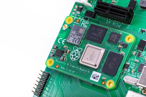
Compute Module 4 mounted on the IO Board
PCB space for additional components
We also wanted to add extra items to the PCB, so PCB space to put the additional parts was an important consideration. If you look carefully at a Compute Module 3 you can see a lot of tracks carrying signals from one side of the SoC to the pins on the edge connector. These tracks take up valuable PCB space, preventing components being fitted there. We could add extra PCB layers to move these tracks from an outer layer to an inner layer, but these extra layers add to the cost of the product.
This was one of the main drivers in changing to having two connectors on different edges of the board: doing so saves having to route tracks all the way across the PCB. So we arrived at a design that incorporated a rough split of which signals were going to end up on each of the connectors. The exact order of the signals wasn’t yet defined.
Trial PCB layouts
We experimented with trial PCB layouts for the Compute Module 4 and the CM4 IO Board to see how easy it would be to route the signals; even at this stage, the final size of the CM4 hadn’t been fixed. Over time, and after juggling parts around the PCB, I came to a sensible compromise. There were lots of things to consider, including the fact that the taller components had to go on the top side of the PCB.
The pinout was constantly being adjusted to an ordering that was a good compromise for both the CM4 and the IO Board. The IO Board layout was a really important consideration: after we made the first prototype boards, we decided to change the pinout slightly to make PCB layout on the IO Board even easier for the end user.
When the prototype Compute Module 4 IO Boards arrived back from manufacture, the connectors hadn’t arrived in time to be assembled by machine, so I fitted them by hand in the lab. Pro tip: if you have to fit connectors by hand, take your time to ensure they are lined up correctly, and use lots of flux to help the solder flow into the joints. Sometimes people use very small soldering iron tips thinking it will help; in fact, one of the goals of soldering is to get heat into the joint, and if the tip is too small it will be difficult to heat the solder joint sufficiently to make a good connection.
Compute Module 4 IO Board
New features
Whilst it was easy to add some headline features like a second HDMI port, other useful features don’t grab as much attention. One example is that we have simplified the powering requirements. Previous Compute Modules required multiple PSUs to power a board, and the power-up sequence had to be exactly correct. Compute Module 4 simply requires a single +5V PSU.
In fact, the simplest possible base board for Compute Module 4 just requires a +5V supply and one of the connectors and nothing else. You would need a CM4 variant with eMMC and wireless connectivity; you can boot the module with the eMMC, wireless connectivity gives you networking, and Bluetooth connectivity gives you access to IO devices. If you do add extra IO devices the CM4 also can provide a +3.3V supply to power those devices, avoiding the need for an external power supply.
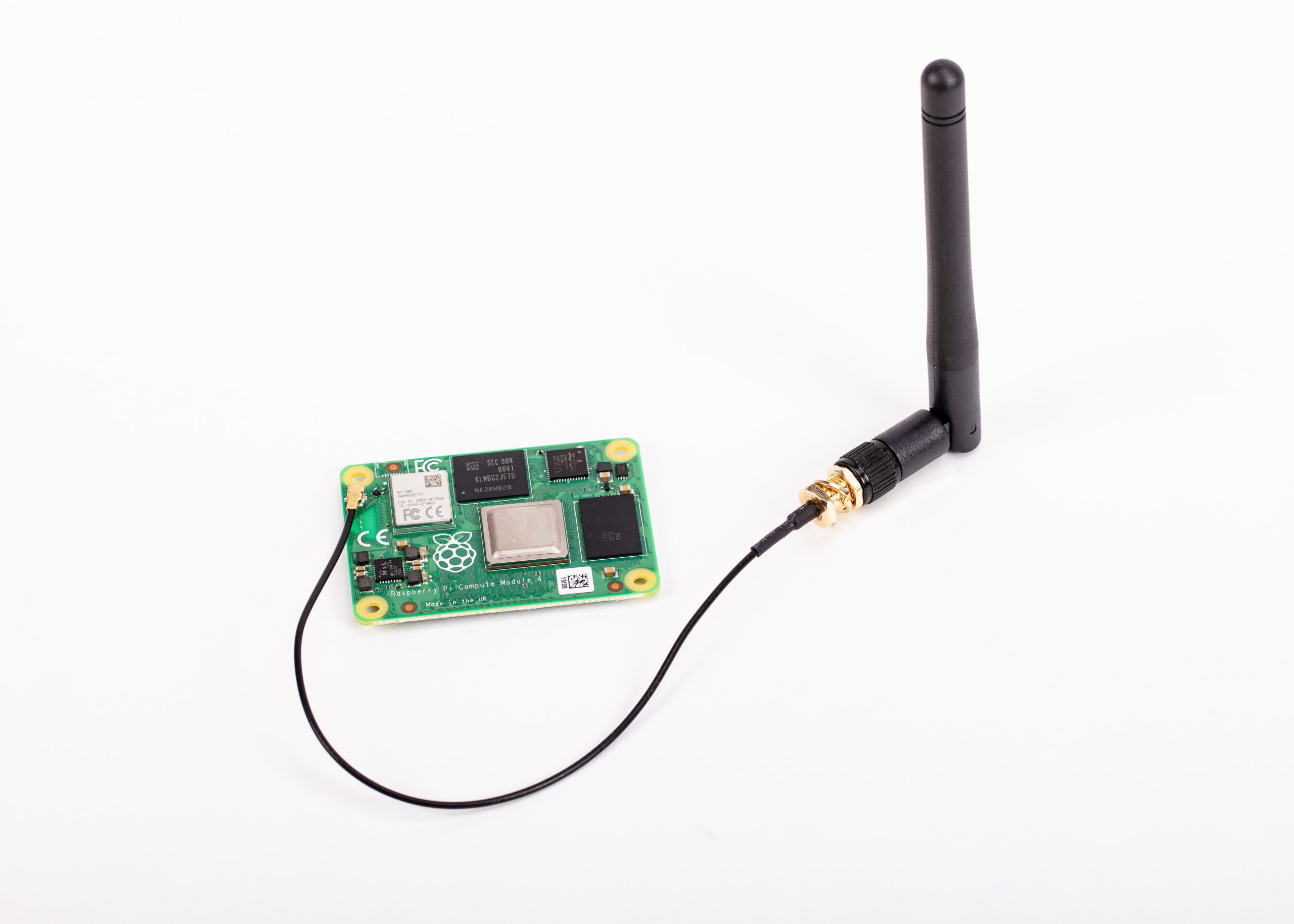
We have seen some customers experience issues with adding wireless interfaces to previous Compute Modules, so a really important requirement was to provide the option of wireless support. We wanted to be as flexible as possible, so we have added support for an external antenna. Because radio certification can be a very hard and expensive process, we have a pre-certified external antenna kit that can be supplied with Compute Module 4. This should greatly simplify product certification for end products, although engineering designers should check to make certain of meeting all local requirements.
Antenna Kit and Compute Module 4
PCIe
This is probably the most exciting new interface to come to Compute Module 4. On the existing Raspberry Pi 4, this interface is used internally to add the XHCI controller which provides the USB 3 ports. By providing the PCIe externally, we are giving end users the choice of how they would like to use this interface. Many applications don’t need USB 3 performance, so the end user can make use of it in other ways — for NVMe drives, to take one example.
Ethernet
In order to have wired Ethernet connectivity with previous Compute Modules, you needed to add an external USB-to-Ethernet interface. This adds complexity to the IO board, and one of the aims of the new Compute Module 4 is to make interfacing to it simple. With this in mind, we added a physical Ethernet interface to CM4, and we also took the opportunity to add support for IEEE1588 to this. As a result, adding Gigabit wired networking to CM4 requires only the addition of a magjack; no extra silicon is needed. Because this is a true Gigabit interface, it is also faster than the USB-to-Ethernet interfaces that previous Compute Modules use.
Open-sourcing the Compute Module 4 IO Board design files
Early on in the process, we decided that we were going to open-source the design files for the Compute Module 4 IO Board. We used our big expensive CAD system for Compute Module 4 itself, and while we could have decided to do the design for the IO Board in the big CAD system too and then port it across to KiCAD, it’s easy to introduce issues in the porting process.
So, instead, we used KiCAD for the IO Board from the start, and the design files that come out of KiCAD are the same ones that we use in manufacture. During development I had both CAD systems running at the same time on the computer.
Easier integration and enhanced possibilities
We have made some big changes to our new Compute Module 4 range, and these should make integration much simpler for our customers. Many interfaces now just need a connector and power, and the new form factor should enable people to design more compact and more powerful products. I look forward to seeing what our customers create over the next few years with Compute Module 4.
High-density connector on board underside
Get your Compute Module 4
The new Raspberry Pi Compute Module 4 is available from our network of Approved Resellers. Head over to the Compute Module 4 product page and select your preferred variant to find your nearest reseller.
Can’t find a reseller near you? No worries. Many of our Approved Resellers ship internationally, so try a few other locations.
Today we have another guest post from Igalia’s Iago Toral, who has spent the past year working on the Mesa graphic driver stack for Raspberry Pi 4.
Four months ago we announced that work on the Vulkan effort for Raspberry Pi 4 (v3dv) was progressing well, and that we were moving the development to an open repository.
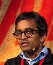
vkQuake3 on Raspberry Pi 4
This week, the Vulkan driver for Raspberry Pi 4 has been merged with Mesa upstream, becoming one of the official Vulkan Mesa drivers. This brings several advantages:
Easier to find: now anyone willing to test the driver just needs to go to the official Mesa repository
Bug tracking: issues/bugs can now be filed on the official Mesa repository bug tracker. If the problem affects other parts of the project, it will be easier for us to involve other Mesa developers.
Releasing: v3dv will be included in all Mesa releases. In due course, you will no longer need to go to an external repository to obtain the driver, as it will be included in the Mesa package for your distribution.
Maintenance: v3dv will be included in the Mesa Continuous Integration system, so every merge request will be tested to ensure that our driver still builds. More effort can go to new features and bug fixes rather than just keeping up with upstream changes.
Progress, and current status
We said back in June that we were passing over 70,000 tests from the Khronos Conformance Test Suite for Vulkan 1.0, and that we had an implementation for a significant subset of the Vulkan 1.0 API. Now we are passing over 100,000 tests, and have implemented the full Vulkan 1.0 API. Only a handful of CTS tests remain to be fixed.
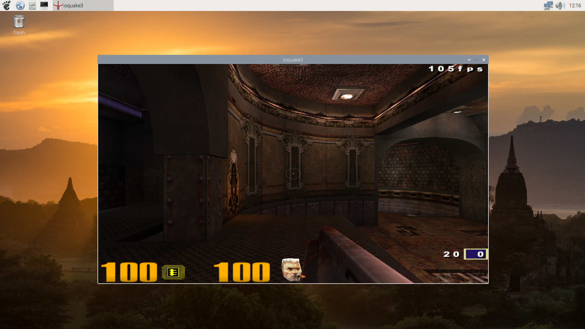
Sascha Willems’ deferred multisampling demo
This doesn’t mean that our work is done, of course. Although the CTS is a really complete test suite, it is not the same as a real use case. As mentioned some of our updates, we have been testing the driver with Vulkan ports of the original Quake trilogy, but deeper and more detailed testing is needed. So the next step will be to test the driver with more use cases, and fixing any bugs or performance issues that we find during the process.
It’s become a tradition that we follow each Raspberry Pi model with a system-on-module variant based on the same core silicon. Raspberry Pi 1 gave rise to the original Compute Module in 2014; Raspberry Pi 3 and 3+ were followed by Compute Module 3 and 3+ in 2017 and 2019 respectively. Only Raspberry Pi 2, our shortest-lived flagship product at just thirteen months, escaped the Compute Module treatment.
It’s been sixteen months since we unleashed Raspberry Pi 4 on the world, and today we’re announcing the launch of Compute Module 4, starting from $25.
Over half of the seven million Raspberry Pi units we sell each year go into industrial and commercial applications, from digital signage to thin clients to process automation. Many of these applications use the familiar single-board Raspberry Pi, but for users who want a more compact or custom form factor, or on-board eMMC storage, Compute Module products provide a simple way to move from a Raspberry Pi-based prototype to volume production.
A step change in performance
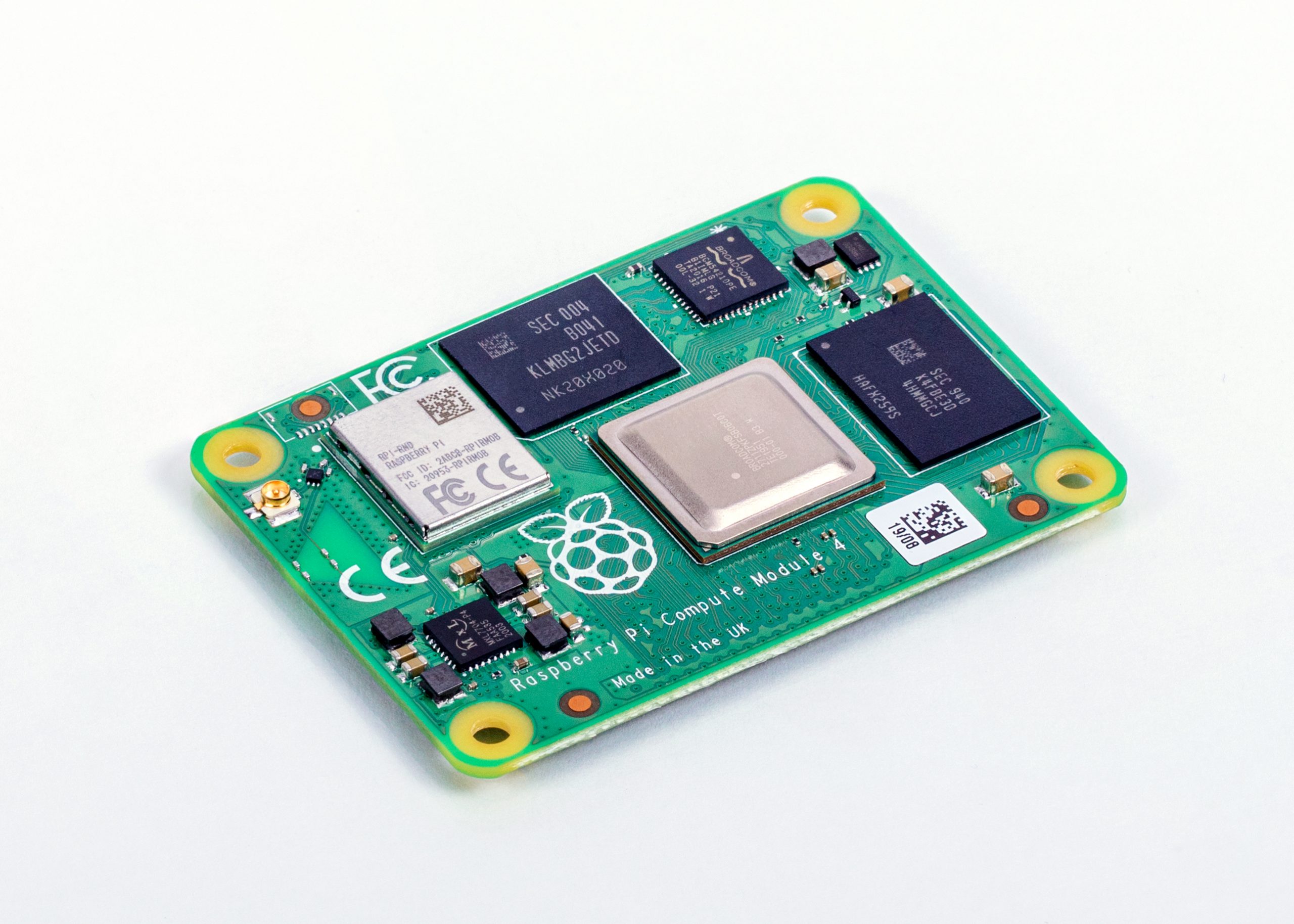
Built on the same 64-bit quad-core BCM2711 application processor as Raspberry Pi 4, our Compute Module 4 delivers a step change in performance over its predecessors: faster CPU cores, better multimedia, more interfacing capabilities, and, for the first time, a choice of RAM densities and a wireless connectivity option.
Raspberry Pi Compute Module 4
You can find detailed specs here, but let’s run through the highlights:
1.5GHz quad-core 64-bit ARM Cortex-A72 CPU
VideoCore VI graphics, supporting OpenGL ES 3.x
4Kp60 hardware decode of H.265 (HEVC) video
1080p60 hardware decode, and 1080p30 hardware encode of H.264 (AVC) video
Dual HDMI interfaces, at resolutions up to 4K
Single-lane PCI Express 2.0 interface
Dual MIPI DSI display, and dual MIPI CSI-2 camera interfaces
1GB, 2GB, 4GB or 8GB LPDDR4-3200 SDRAM
Optional 8GB, 16GB or 32GB eMMC Flash storage
Optional 2.4GHz and 5GHz IEEE 802.11b/g/n/ac wireless LAN and Bluetooth 5.0
Gigabit Ethernet PHY with IEEE 1588 support
28 GPIO pins, with up to 6 × UART, 6 × I2C and 5 × SPI
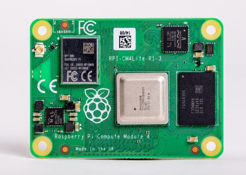
Compute Module 4 Lite, our variant without eMMC Flash memory
New, more compact form factor
Compute Module 4 introduces a brand new form factor, and a compatibility break with earlier Compute Modules. Where previous modules adopted the JEDEC DDR2 SODIMM mechanical standard, with I/O signals on an edge connector, we now bring I/O signals to two high-density perpendicular connectors (one for power and low-speed interfaces, and one for high-speed interfaces).
This significantly reduces the overall footprint of the module on its carrier board, letting you achieve smaller form factors for your products.
High-density connector on board underside
32 variants
With four RAM options, four Flash options, and optional wireless connectivity, we have a total of 32 variants, with prices ranging from $25 (for the 1GB RAM, Lite, no wireless variant) to $90 (for the 8GB RAM, 32GB Flash, wireless variant).
We’re very pleased that the four variants with 1GB RAM and no wireless keep the same price points ($25, $30, $35, and $40) as their Compute Module 3+ equivalents: once again, we’ve managed to pack a lot more performance into the platform without increasing the price.
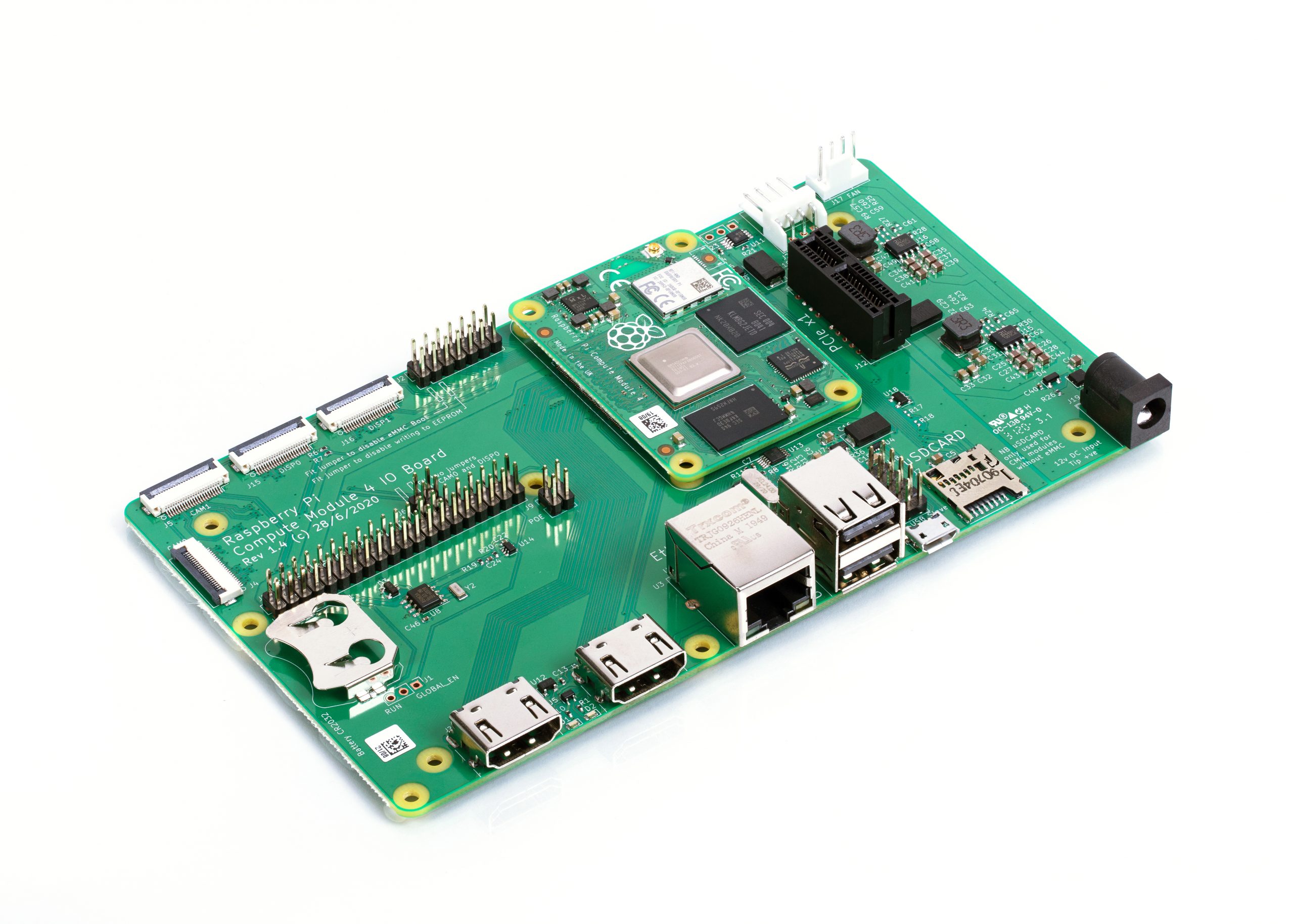
To help you get started with Compute Module 4, we are also launching an updated IO Board. Like the IO boards for earlier Compute Module products, this breaks out all the interfaces from the Compute Module to standard connectors, providing a ready-made development platform and a starting point for your own designs.
Compute Module 4 IO Board
The IO board provides:
Two full-size HDMI ports
Gigabit Ethernet jack
Two USB 2.0 ports
MicroSD card socket (only for use with Lite, no-eMMC Compute Module 4 variants)
PCI Express Gen 2 x1 socket
HAT footprint with 40-pin GPIO connector and PoE header
12V input via barrel jack (supports up to 26V if PCIe unused)
Camera and display FPC connectors
Real-time clock with battery backup
CAD for the IO board is available in KiCad format. You may recall that a few years ago we made a donation to support improvements to KiCad’s differential pair routing and track length control features; now you can use this feature-rich, open-source PCB layout package to design your own Compute Module carrier board.
Compute Module 4 mounted on the IO Board
In addition to serving as a development platform and reference design, we expect the IO board to be a finished product in its own right: if you require a Raspberry Pi that supports a wider range of input voltages, has all its major connectors in a single plane, or allows you to attach your own PCI Express devices, then Compute Module 4 with the IO Board does what you need.
We’ve set the price of the bare IO board at just $35, so a complete package including a Compute Module starts from $60.
Compute Module 4 Antenna Kit
We expect that most users of wireless Compute Module variants will be happy with the on-board PCB antenna. However, in some circumstances – for example, where the product is in a metal case, or where it is not possible to provide the necessary ground plane cut-out under the module – an external antenna will be required. The Compute Module 4 Antenna Kit comprises a whip antenna, with a bulkhead screw fixture and U.FL connector to attach to the socket on the module.
Antenna Kit and Compute Module 4
When using ether the Antenna Kit or the on-board antenna, you can take advantage of our modular certification to reduce the conformance testing costs for your finished product. And remember, the Raspberry Pi Integrator Programme is there to help you get your Compute Module-based product to market.
Our most powerful Compute Module
This is our best Compute Module yet. It’s also our first product designed by Dominic Plunkett, who joined us almost exactly a year ago.
I sat down with Dominic last week to discuss Compute Module 4 in greater detail, and you can find the video of our conversation here. Dominic will also be sharing more technical detail in the blog tomorrow.
In the meantime, check out the Compute Module 4 page for the datasheet and other details, and start thinking about what you’ll build with Compute Module 4.
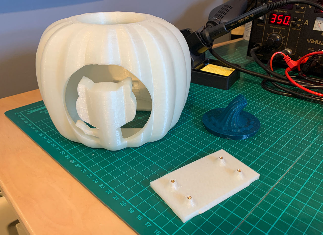
Following on from Rob Zwetsloot’s Haunted House Hacks in the latest issue of The MagPi magazine, GitHub’s Martin Woodward has created a spooky pumpkin that warns you about the thing programmers find scariest of all — broken builds. Here’s his guest post describing the project:
“When you are browsing code looking for open source projects, seeing a nice green passing build badge in the ReadMe file lets you know everything is working with the latest version of that project. As a programmer you really don’t want to accidentally commit bad code, which is why we often set up continuous integration builds that constantly check the latest code in our project.”
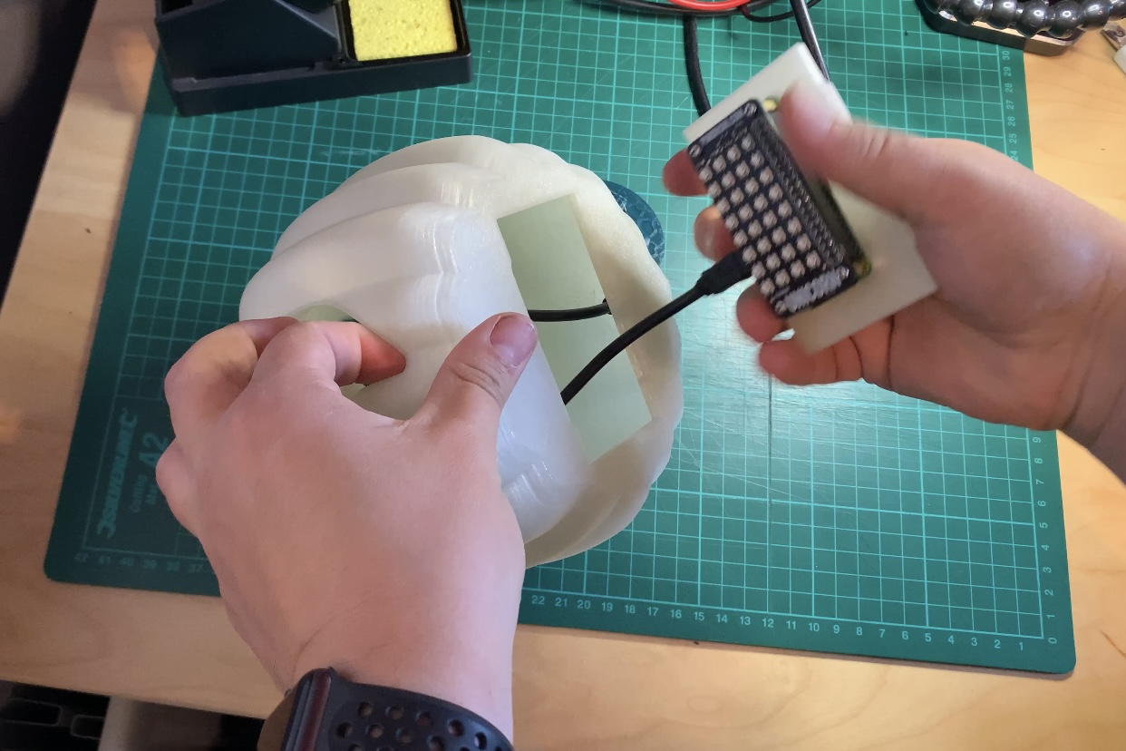
“I decided to create a 3D-printed pumpkin that would hold a Raspberry Pi Zero with an RGB LED pHat on top to show me the status of my build for Halloween. All the code is available on GitHub alongside the 3D printing models which are also available on Thingiverse.”
Components
Raspberry Pi Zero (I went for the WH version to save me soldering on the header pins)
Unicorn pHat from Pimoroni
Panel mount micro-USB extension
M2.5 hardware for mounting (screws, male PCB standoffs, and threaded inserts)
“For the 3D prints, I used a glow-in-the-dark PLA filament for the main body and Pi holder, along with a dark green PLA filament for the top plug.”
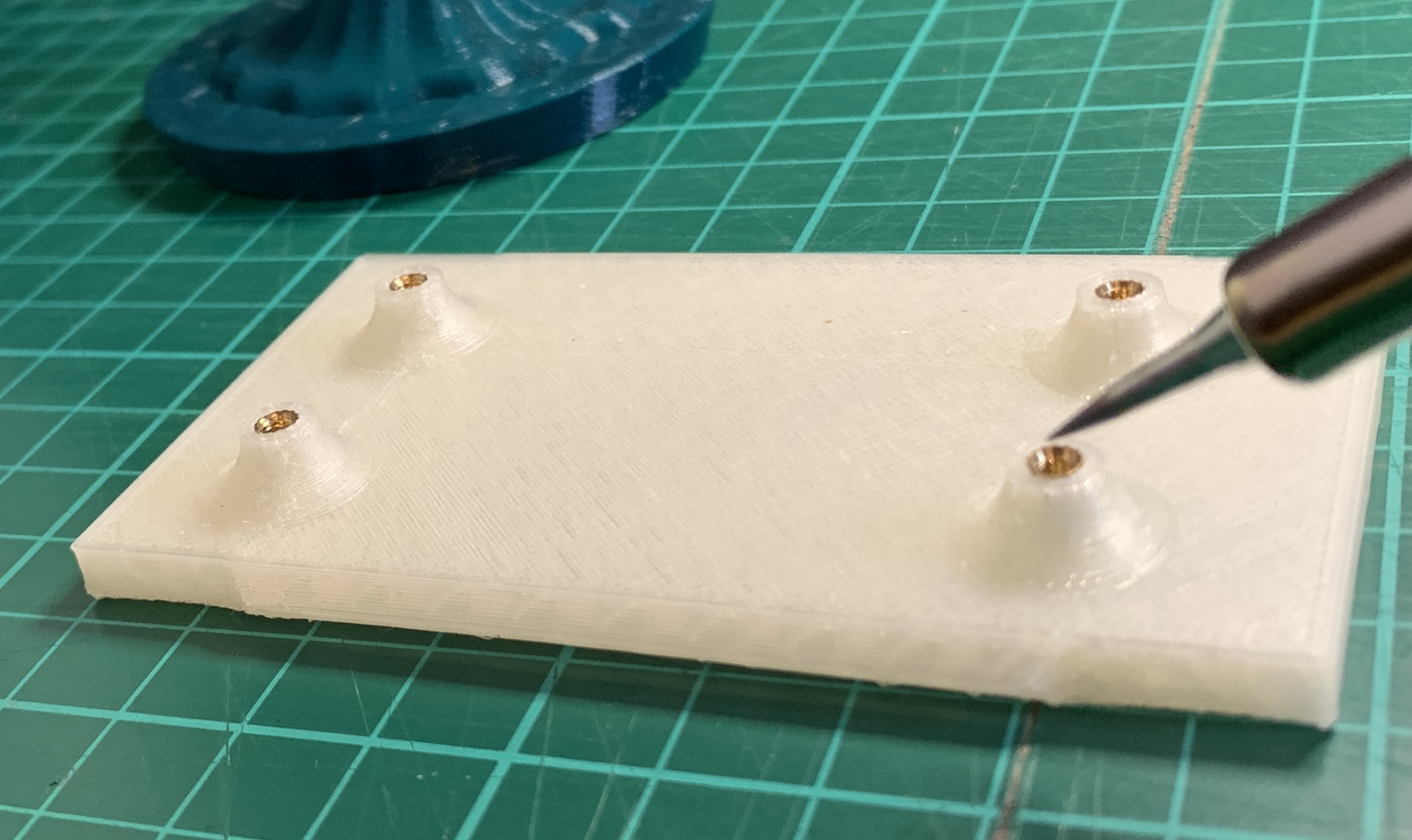
“I’ve been using M2.5 threaded inserts quite a bit when printing parts to fit a Raspberry Pi, as it allows you to simply design a small hole in your model and then you push the brass thread into the gap with your soldering iron to melt it securely into place ready for screwing in your device.”
Threaded insert
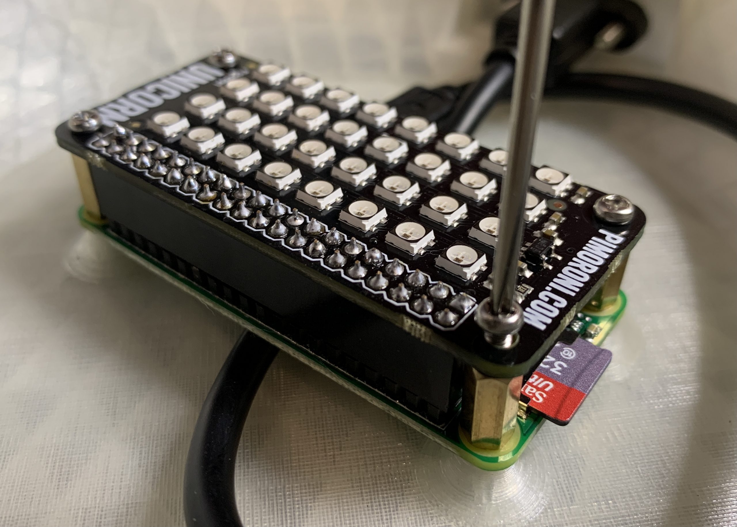
“Once the inserts are in, you can screw the Raspberry Pi Zero into place using some brass PCB stand-offs, place the Unicorn pHAT onto the GPIO ports, and then screw that down.”
pHAT install
“Then you screw in the panel-mounted USB extension into the back of the pumpkin, connect it to the Raspberry Pi, and snap the Raspberry Pi holder into place in the bottom of your pumpkin.”
Inserting the base
Code along with Martin
“Now you are ready to install the software. You can get the latest version from my PumpkinPi project on GitHub. “
“Format the micro SD Card and install Raspberry Pi OS Lite. Rather than plugging in a keyboard and monitor, you probably want to do a headless install, configuring SSH and WiFi by dropping an ssh file and a wpa_supplicant.conf file onto the root of the SD card after copying over the Raspbian files.”
“You’ll need to install the Unicorn HAT software, but they have a cool one-line installer that takes care of all the dependencies including Python and Git.”
# How often to check (in seconds). Remember - be nice to the server. Once every 5 minutes is plenty.
REFRESH_INTERVAL = 300
“Finally you can run the script as root:”
sudo python ~/PumpkinPi/src/pumpkinpi.py &
“Once you are happy everything is running how you want, don’t forget you can run the script at boot time. The easiest way to do this is to use crontab. See this cool video from Estefannie to learn more. But basically you do sudo crontab -e then add the following:”
“Note that we are pausing for 10 seconds before running the Python script. This is to allow the WiFi network to connect before we check on the state of our build.”
“The current version of the pumpkinpi script works with all the SVG files produced by the major hosted build providers, including GitHub Actions, which is free for open source projects. But if you want to improve the code in any way, I’m definitely accepting pull requests on it.”
“Using the same hardware you could monitor lots of different things, such as when someone posts on Twitter, what the weather will be tomorrow, or maybe just code your own unique multi-coloured display that you can leave flickering in your window.”
“If you build this project or create your own pumpkin display, I’d love to see pictures. You can find me on Twitter @martinwoodward and on GitHub.”
The Bebras Challenge is a great way for your students to practise their computational thinking skills while solving exciting, accessible, and puzzling questions. Usually this 40-minute challenge would take place in the classroom. However, this year for the first time, your students can participate from home too!
If your students haven’t entered before, now is a great opportunity for them to get involved: they don’t need any prior knowledge.
Do you have any students who are up for tackling the Bebras Challenge? Then register your school today!
What you need to know about the Bebras Challenge
It’s a great whole-school activity open to students aged 6 to 18, in different age group categories.
It’s completely free!
The closing date for registering your school is 30 October.
Let your students complete the challenge between 2 and 13 November 2020.
The challenge is made of a set of short tasks, and completing it takes 40 minutes.
The challenge tasks focus on logical thinking and do not require any prior knowledge of computer science.
There are practice questions to help your students prepare for the challenge.
This year, students can take part at home (please note they must still be entered through their school).
All the marking is done for you! The results will be sent to you the week after the challenge ends, along with the answers, so that you can go through them with your students.
“Thank you for another super challenge. It’s one of the highlights of my year as a teacher. Really, really appreciate the high-quality materials, website, challenge, and communication. Thank you again!”
– A UK-based teacher
Support your students to develop their computational thinking skills with Bebras materials
Bebras is an international challenge that started in Lithuania in 2004 and has grown into an international event. The UK became involved in Bebras for the first time in 2013, and the number of participating students has increased from 21,000 in the first year to more than 260,000 last year! Internationally, nearly 3 million learners took part in 2019.
Bebras is a great way to engage your students of all ages in problem-solving and give them a taste of what computing is all about. In the challenge results, computing principles are highlighted, so Bebras can be educational for you as a teacher too.
The annual Bebras Challenge is only one part of the equation: questions from previous years are available as a resource that you can use to create self-marking quizzes for your classes. You can use these materials throughout the year to help you to deliver the computational thinking part of your curriculum!
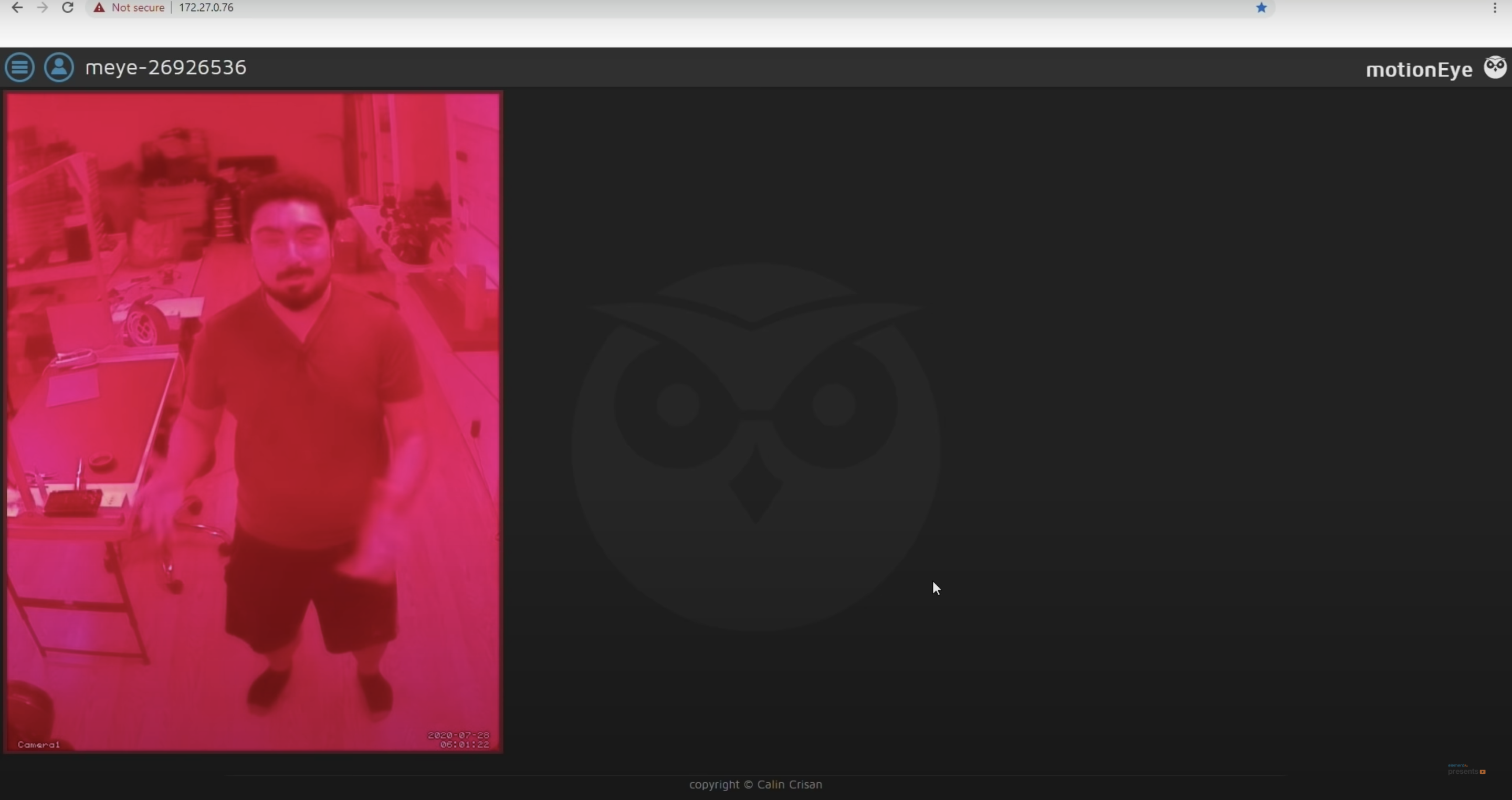
DJ from the element14 community shows you how to build a red-lensed security camera in the style of Portal 2 using the Raspberry Pi High Quality Camera.
The finished camera mounted on the wall
Portal 2 is a puzzle platform game developed by Valve — a “puzzle game masquerading as a first-person shooter”, according to Forbes.
DJ playing with the Raspberry Pi High Quality Camera
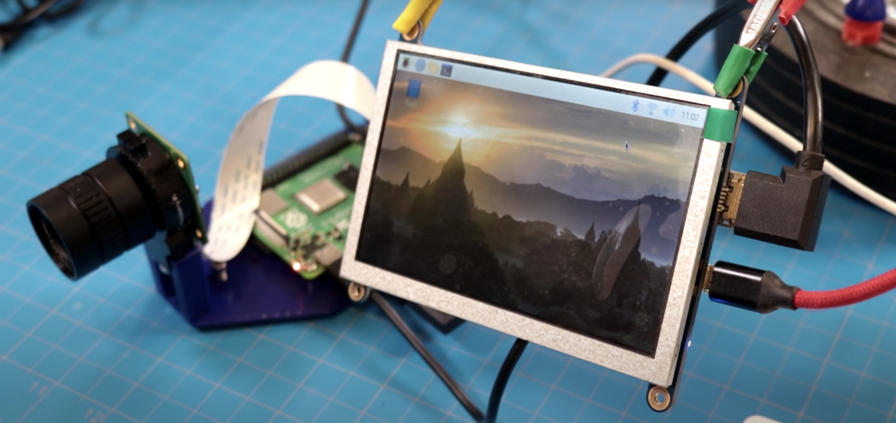
DJ was pleased to learn that you don’t need to write any code to make your own security camera, you can just use a package called motionEyeOS. All you have to do is download the motionEyeOS image, pop the flashed SD card into your Raspberry Pi, and you’re pretty much good to go.
Dj got everything set up on a 5″ screen attached to the Raspberry Pi
You’ll find that the default resolution is 640×480, so it will show up as a tiny window on your monitor of choice, but that can be amended.
Simplicity
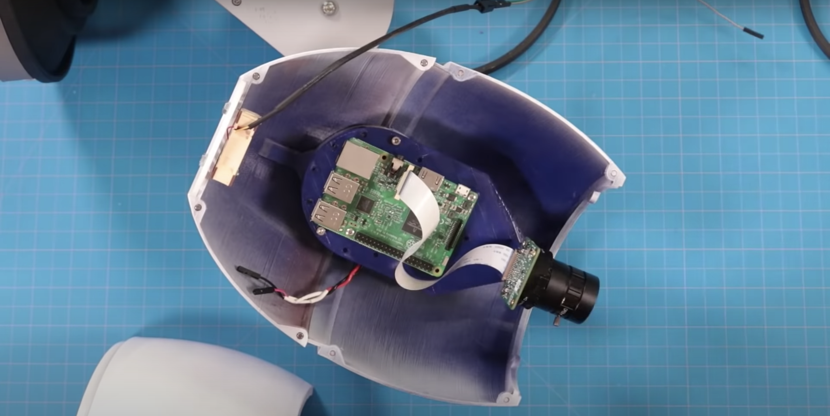
While this build is very simple electronically, the 20-part 3D-printed shell is beautiful. A Raspberry Pi is positioned on a purpose-built platform in the middle of the shell, connected to the Raspberry Pi High Quality Camera, which sits at the front of that shell, peeking out.
All the 3D printed parts ready to assemble
The 5V power supply is routed through the main shell into the base, which mounts the build to the wall. In order to keep the Raspberry Pi cool, DJ made some vent holes in the lens of the shell. The red LED is routed out of the side and sits on the outside body of the shell.
Magnetising
Raspberry Pi 4 (centre) and Raspberry Pi High Quality Camera (right) sat inside the 3D printed shell
This build is also screwless: the halves of the shell have what look like screw holes along the edges, but they are actually 3mm neodymium magnets, so assembly and repair is super easy as everything just pops on and off.
The final picture (that’s DJ!)
You can find all the files you need to recreate this build, or you can ask DJ a question, at element14.com/presents.
Discover how non-player characters make decisions by tinkering with this Unity-based Pac-Man homage. Paul Roberts wrote this for the latest issue of Wireframe magazine.
From the first video game to the present, artificial intelligence has been a vital part of the medium. While most early games had enemies that simply walked left and right, like the Goombas in Super Mario Bros., there were also games like Pac-Man, where each ghost appeared to move intelligently. But from a programming perspective, how do we handle all the different possible states we want our characters to display?
Here’s AI-Man, our homage to a certain Namco maze game. You can switch between AI types to see how they affect the ghosts’ behaviours.
For example, how do we control whether a ghost is chasing Pac-Man, or running away, or even returning to their home? To explore these behaviours, we’ll be tinkering with AI-Man – a Pac-Man-style game developed in Unity. It will show you how the approaches discussed in this article are implemented, and there’s code available for you to modify and add to. You can freely download the AI-Man project here. One solution to managing the different states a character can be in, which has been used for decades, is a finite state machine, or FSM for short. It’s an approach that describes the high-level actions of an agent, and takes its name simply from the fact that there are a finite number of states from which to transition between, with each state only ever doing one thing.
Altered states
To explain what’s meant by high level, let’s take a closer look at the ghosts in Pac-Man. The highlevel state of a ghost is to ‘Chase’ Pac-Man, but the low level is how the ghost actually does this. In Pac-Man, each ghost has its own behaviour in which it hunts the player down, but they’re all in the same high-level state of ‘Chase’. Looking at Figure 1, you can see how the overall behaviour of a ghost can be depicted extremely easily, but there’s a lot of hidden complexity. At what point do we transition between states? What are the conditions on moving between states across the connecting lines? Once we have this information, the diagram can be turned into code with relative ease. You could use simple switch statements to achieve this, or we could achieve the same using an object-oriented approach.
Figure 1: A finite state machine
Using switch statements can quickly become cumbersome the more states we add, so I’ve used the object-oriented approach in the accompanying project, and an example code snippet can be seen in Code Listing 1. Each state handles whether it needs to transition into another state, and lets the state machine know. If a transition’s required, the Exit() function is called on the current state, before calling the Enter() function on the new state. This is done to ensure any setup or cleanup is done, after which the Update() function is called on whatever the current state is. The Update()function is where the low-level code for completing the state is processed. For a project as simple as Pac-Man, this only involves setting a different position for the ghost to move to.
Hidden complexity
Extending this approach, it’s reasonable for a state to call multiple states from within. This is called a hierarchical finite state machine, or HFSM for short. An example is an agent in Call of Duty: Strike Team being instructed to seek a stealthy position, so the high-level state is ‘Find Cover’, but within that, the agent needs to exit the dumpster he’s currently hiding in, find a safe location, calculate a safe path to that location, then repeatedly move between points on that path until he reaches the target position.
FSMs can appear somewhat predictable as the agent will always transition into the same state. This can be accommodated for by having multiple options that achieve the same goal. For example, when the ghosts in our Unity project are in the ‘Chase’ state, they can either move to the player, get in front of the player, or move to a position behind the player. There’s also an option to move to a random position. The FSM implemented has each ghost do one of these, whereas the behaviour tree allows all ghosts to switch between the options every ten seconds. A limitation of the FSM approach is that you can only ever be in a single state at a particular time. Imagine a tank battle game where multiple enemies can be engaged. Simply being in the ‘Retreat’ state doesn’t look smart if you’re about to run into the sights of another enemy. The worst-case scenario would be our tank transitions between ‘Attack’ and ‘Retreat’ states on each frame – an issue known as state thrashing – and gets stuck, and seemingly confused about what to do in this situation. What we need is away to be in multiple states at the same time: ideally retreating from tank A, whilst attacking tank B. This is where fuzzy finite state machines, or FFSM for short, come in useful.
This approach allows you to be in a particular state to a certain degree. For example, my tank could be 80% committed to the Retreat state (avoid tank A), and 20% committed to the Attack state (attack tank B). This allows us to both Retreat and Attack at the same time. To achieve this, on each update, your agent needs to check each possible state to determine its degree of commitment, and then call each of the active states’ updates. This differs from a standard FSM, where you can only ever be in a single state. FFSMs can be in none, one, two, or however many states you like at one time. This can prove tricky to balance, but it does offer an alternative to the standard approach.
No memory
Another potential issue with an FSM is that the agent has no memory of what they were previously doing. Granted, this may not be important: in the example given, the ghosts in Pac-Man don’t care about what they were doing, they only care about what they are doing, but in other games, memory can be extremely important. Imagine instructing a character to gather wood in a game like Age of Empires, and then the character gets into a fight. It would be extremely frustrating if the characters just stood around with nothing to do after the fight had concluded, and for the player to have to go back through all these characters and reinstruct them after the fight is over. It would be much better for the characters to return to their previous duties.
“FFSMs can be in one, none,
two, or however many states
you like.”
We can incorporate the idea of memory quite easily by using the stack data structure. The stack will hold AI states, with only the top-most element receiving the update. This in effect means that when a state is completed, it’s removed from the stack and the previous state is then processed. Figure 2 depicts how this was achieved in our Unity project. To differentiate the states from the FSM approach, I’ve called them tasks for the stackbased implementation. Looking at Figure 2, it shows how (from the bottom), the ghost was chasing the player, then the player collected a power pill, which resulted in the AI adding an Evade_Task – this now gets the update call, not the Chase_Task. While evading the player, the ghost was then eaten.
At this point, the ghost needed to return home, so the appropriate task was added. Once home, the ghost needed to exit this area, so again, the relevant task was added. At the point the ghost exited home, the ExitHome_Task was removed, which drops processing back to MoveToHome_Task. This was no longer required, so it was also removed. Back in the Evade_Task, if the power pill was still active, the ghost would return to avoiding the player, but if it had worn off, this task, in turn, got removed, putting the ghost back in its default task of Chase_Task, which will get the update calls until something else in the world changes.
Figure 2: Stack-based finite state machine.
Behaviour trees
In 2002, Halo 2 programmer Damian Isla expanded on the idea of HFSM in a way that made it more scalable and modular for the game’s AI. This became known as the behaviour tree approach. It’s now a staple in AI game development. The behaviour tree is made up of nodes, which can be one of three types – composite, decorator, or leaf nodes. Each has a different function within the tree and affects the flow through the tree. Figure 3 shows how this approach is set up for our Unity project. The states we’ve explored so far are called leaf nodes. Leaf nodes end a particular branch of the tree and don’t have child nodes – these are where the AI behaviours are located. For example, Leaf_ExitHome, Leaf_Evade, and Leaf_ MoveAheadOfPlayer all tell the ghost where to move to. Composite nodes can have multiple child nodes and are used to determine the order in which the children are called. This could be in the order in which they’re described by the tree, or by selection, where the children nodes will compete, with the parent node selecting which child node gets the go-ahead. Selector_Chase allows the ghost to select a single path down the tree by choosing a random option, whereas Sequence_ GoHome has to complete all the child paths to complete its behaviour.
Code Listing 2 shows how simple it is to choose a random behaviour to use – just be sure to store the index for the next update. Code Listing 3 demonstrates how to go through all child nodes, and to return SUCCESS only when all have completed, otherwise the status RUNNING is returned. FAILURE only gets returned when a child node itself returns a FAILURE status.
Complex behaviours
Although not used in our example project, behaviour trees can also have nodes called decorators. A decorator node can only have a single child, and can modify the result returned. For example, a decorator may iterate the child node for a set period, perhaps indefinitely, or even flip the result returned from being a success to a failure. From what first appears to be a collection of simple concepts, complex behaviours can then develop.
Figure 3: Behaviour tree
Video game AI is all about the illusion of intelligence. As long as the characters are believable in their context, the player should maintain their immersion in the game world and enjoy the experience we’ve made. Hopefully, the approaches introduced here highlight how even simple approaches can be used to develop complex characters. This is just the tip of the iceberg: AI development is a complex subject, but it’s also fun and rewarding to explore.
Wireframe #43, with the gorgeous Sea of Stars on the cover.