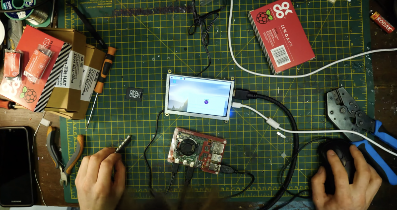
With so many people all over the world still living in various levels of lockdown, we’ve been working hard to provide free, creative project resources for you to keep young digital makers occupied, learning, and most importantly having fun.
As a dad of two, I know how useful it is to have resources and project ideas for things that we can do together, or that the kids can crack on with independently. As we head into the weekend, I thought I’d share a few ideas for where to get started.
Coding and digital making projects
We offer hundreds of self-guided projects for learning to create with code using tools like Scratch, Python, and more. The projects can be completed online on any computer, they are tailored for different levels of experience, and they include step-by-step guidance that quickly leads to confident, independent young digital makers.
You can code a butterfly garden with one of our ‘Look after yourself’ projects!
We recently launched a new set of beginner Scratch projects on the theme of ‘Look after yourself’, which include activities designed to help young people take care of their own wellbeing while getting creative with code. They are brilliant.
“I am so excited by the [‘Look after yourself’] projects on offer. It couldn’t be more perfect for everything we are navigating right now.”
If Earth is getting you down, then how about creating code that will be sent to the International Space Station?
This is where your kids’ code could run aboard the ISS!
As part of Astro Pi Mission Zero, young people up to age 14 can write a Python program to send their own personal message to the astronauts aboard the ISS. Mission Zero takes about an hour to complete online following a step-by-step guide. It’s a fantastic activity for anyone looking to write Python code for the first time!
Make a cool project
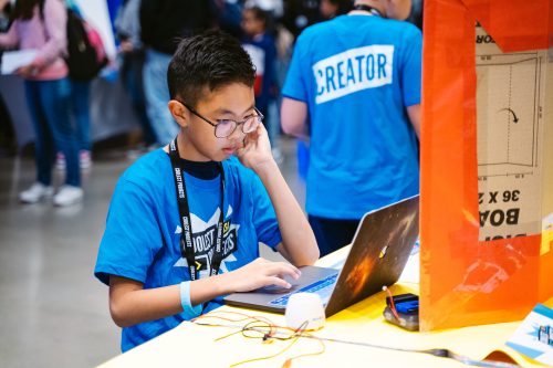
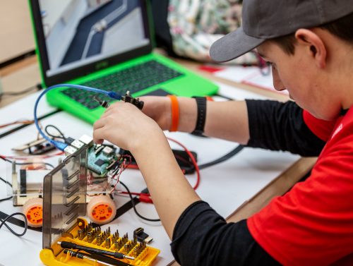
We know that motivation matters. Young digital makers often need a goal to work towards, and that’s where Coolest Projects comes in. It’s the world-leading technology showcase where young digital makers show the world what they’ve created and inspire each other.
Coolest Projects is open to young people up to the age of 18, all over the world, with any level of experience or skills. Young people can register their project ideas now and then create their project so that they can share it with the world on our online gallery.
It’s a brilliant way to motivate your young digital makers to come up with an idea and make it real. If you’re looking for inspiration, then check out the brilliant projects from last year.
Happy digital making!
I hope that these resources and project ideas inspire you and your kids to get creative with technology, whether you’re in lockdown or not. Stay safe and be kind to yourself and each other. We’ll get through this.
Speed around an arena, avoiding walls and deadly trails in this Light Cycle minigame. Mark Vanstone has the code.
Battle against AI enemies in the original arcade classic.
At the beginning of the 1980s, Disney made plans for an entirely new kind of animated movie that used cutting-edge computer graphics. The resulting film was 1982’s TRON, and it inevitably sparked one of the earliest tie-in arcade machines.
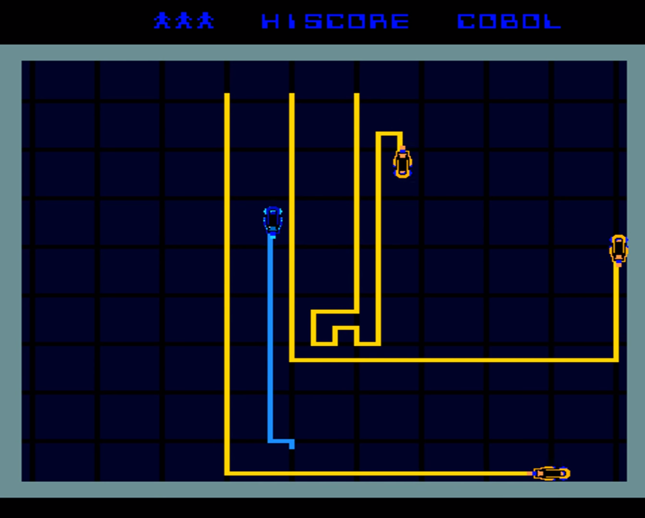
The game featured several minigames, including one based on the Light Cycle section of the movie, where players speed around an arena on high-tech motorbikes, which leave a deadly trail of light in their wake. If competitors hit any walls or cross the path of any trails, then it’s game over.
Players progress through the twelve levels which were all named after programming languages. In the Light Cycle game, the players compete against AI players who drive yellow Light Cycles around the arena. As the levels progress, more AI Players are added.
The TRON game, distributed by Bally Midway, was well-received in arcades, and even won Electronic Games Magazine’s (presumably) coveted Coin-operated Game of the Year gong.
Although the arcade game wasn’t ported to home computers at the time, several similar games – and outright clones – emerged, such as the unsubtly named Light Cycle for the BBC Micro, Oric, and ZX Spectrum.
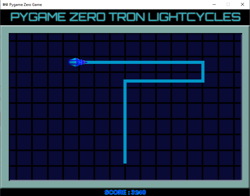
The Light Cycle minigame is essentially a variation on Snake, with the player leaving a trail behind them as they move around the screen. There are various ways to code this with Pygame Zero.
In this sample, we’ll focus on the movement of the player Light Cycle and creating the trails that are left behind as it moves around the screen. We could use line drawing functions for the trail behind the bike, or go for a system like Snake, where blocks are added to the trail as the player moves.
In this example, though, we’re going to use a two-dimensional list as a matrix of positions on the screen. This means that wherever the player moves on the screen, we can set the position as visited or check to see if it’s been visited before and, if so, trigger an end-game event.
Our homage to the TRON Light Cycle classic arcade game.
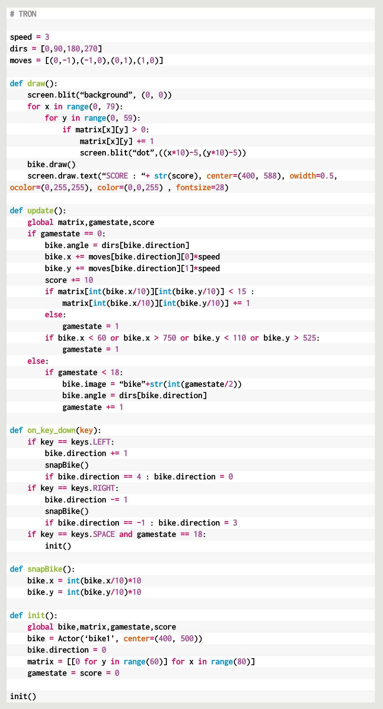
For the main draw() function, we first blit our background image which is the cross-hatched arena, then we iterate through our two-dimensional list of screen positions (each 10 pixels square) displaying a square anywhere the Cycle has been. The Cycle is then drawn and we can add a display of the score.
The update() function contains code to move the Cycle and check for collisions. We use a list of directions in degrees to control the angle the player is pointing, and another list of x and y increments for each direction. Each update we add x and y coordinates to the Cycle actor to move it in the direction that it’s pointing multiplied by our speed variable.
We have an on_key_down() function defined to handle changing the direction of the Cycle actor with the arrow keys. We need to wait a while before checking for collisions on the current position, as the Cycle won’t have moved away for several updates, so each screen position in the matrix is actually a counter of how many updates it’s been there for.
We can then test to see if 15 updates have happened before testing the square for collisions, which gives our Cycle enough time to clear the area. If we do detect a collision, then we can start the game-end sequence.
We set the gamestate variable to 1, which then means the update() function uses that variable as a counter to run through the frames of animation for the Cycle’s explosion. Once it reaches the end of the sequence, the game stops.
We have a key press defined (the SPACE bar) in the on_key_down() function to call our init() function, which will not only set up variables when the game starts but sets things back to their starting state.
Here’s Mark’s code for a TRON-style Light Cycle minigame. To get it working on your system, you’ll need to install Pygame Zero. And to download the full code and assets, head here.
So that’s the fundamentals of the player Light Cycle movement and collision checking. To make it more like the original arcade game, why not try experimenting with the code and adding a few computer-controlled rivals?
Get your copy of Wireframe issue 47
You can read more features like this one in Wireframe issue 47, available directly from Raspberry Pi Press — we deliver worldwide.
And if you’d like a handy digital version of the magazine, you can also download issue 47 for free in PDF format.
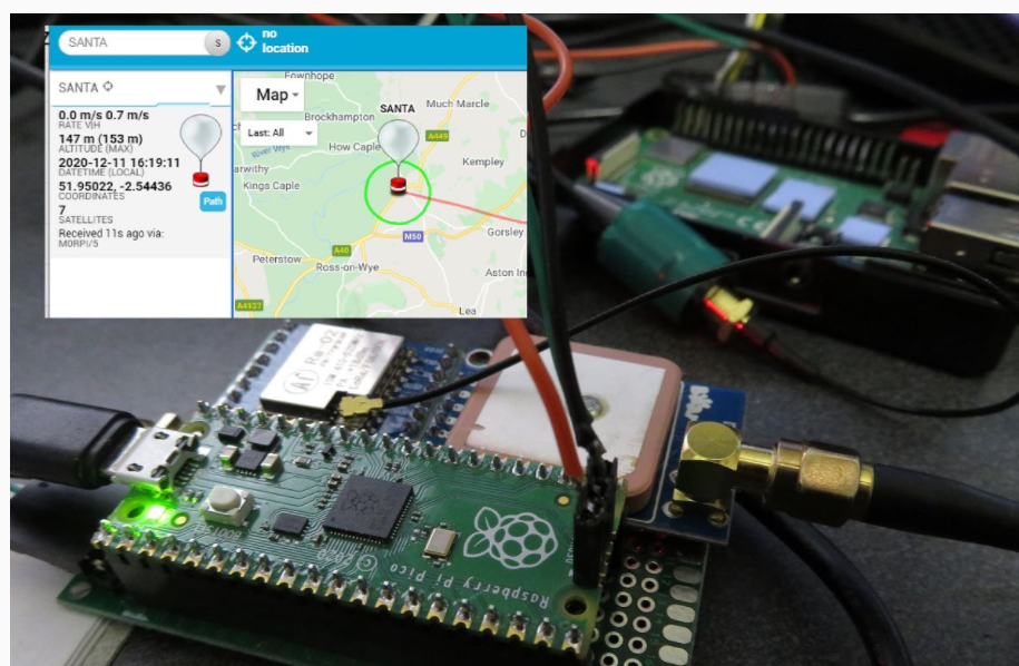
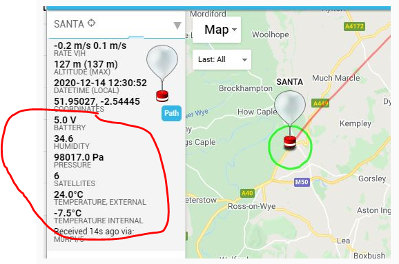
Dave Akerman of High Altitude Ballooning came up with a stratospherically cool application for Raspberry Pi Pico. In this guest blog, he shows you how to build and code a weather balloon tracker.
Balloon tracking
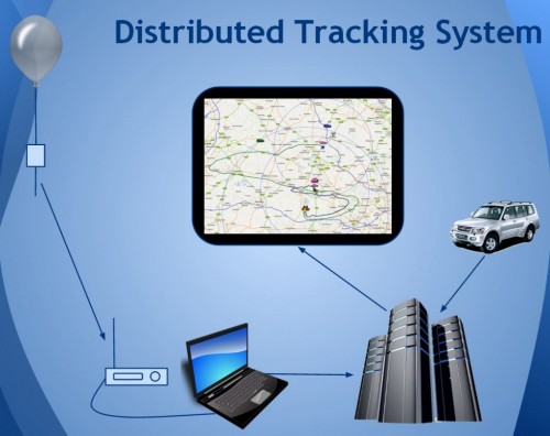
My main hobby is flying weather balloons, using GPS/radio trackers to relay their position to the ground, so they can be tracked and hopefully recovered. Trackers minimally consist of a GPS receiver feeding the current position to a small computer, which in turn controls a radio transmitter to send that position to the ground. That position is then fed to a live map to aid chasing and recovering the flight.
How it all works
This essential role of the tracker computer is thus a simple one, and those making their own trackers can choose from a variety of microcontrollers chips and boards, for example Arduino boards, PIC microcontrollers or the BBC Microbit. Anything with a modest amount of code memory, data memory, processor power and I/O (serial, SPI etc depending on choice of GPS and radio) will do. A popular choice is Raspberry Pi, which, whilst a sledgehammer to crack a nut for tracking, does make it easy to add a camera.
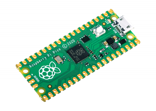
Raspberry Pi Pico
When I see a new type of processor board, I feel duty bound to make it into a balloon tracker, so when I was asked to help test the new Raspberry Pi Pico, doing so was my first thought. It has plenty of I/O – SPI ports, I2C and serial all available – plus a unique ability (not that I need it for now) to add extra peripherals using the programmable PIO modules, so there was no doubt that it would be very usable. Also, having much more memory than typical microcontrollers, it offers the ability to add functions that would normally need a full Raspberry Pi board – for example on-board landing prediction. More on that later.
Tracker components
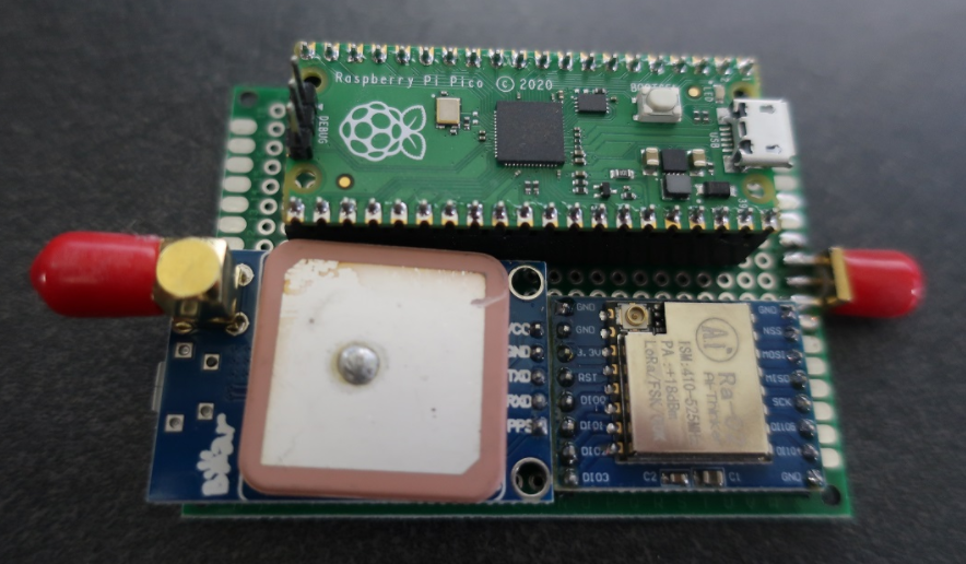
So a basic tracker has a GPS receiver and radio transmitter. To connect these to the Raspberry Pi Pico, I used a prototyping board where I mounted a UBlox GPS receiver, LoRa radio transmitter, and sockets for the Pico itself.
I don’t use breadboards as they are prone to intermittent connections that then waste programming time chasing a “bug” that’s actually a hardware problem. Besides, trackers need to be robust so I would need to solder one together eventually anyway.
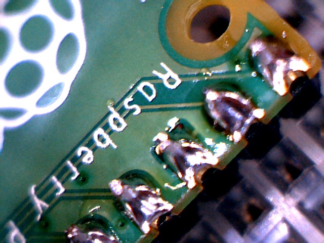
Pico top, GPS bottom-left; LoRa bottom-right
The particular UBlox GPS module I had handy only has a serial port brought out, so I couldn’t use I2C. No matter because, unlike most Arduino boards, the Raspberry Pi Pico isn’t limited to a single serial port.
The LoRa module connects via SPI and a single GPIO pin which the module uses to send its status (e.g. packet sent – ready to send next packet) to the Raspberry Pi Pico.
Finally, with the tracker working, I added an I2C environmental sensor to the board via a pin header, so the sensor can be placed in free air outside the tracker.
Finally, with the tracker working, I added an I2C environmental sensor to the board via a pin header, so the sensor can be placed in free air outside the tracker.
Development setup
I decided to use C for my tracker rather than Python, for a variety of reasons. The main one is that I have plenty of existing C tracker code to work from, for Arduino and Raspberry Pi, but not so much Python. Secondly, I figured that most of the testers would be using Python so there might be more of a need to test the C toolchain.
The easiest route to getting the C/C++ toolchain working is to install on a Raspberry Pi 4. I couldn’t quite get the VSCode integration working (finger trouble I think) but anyway I’m quite happy to code with an editor and separate build window. So what I ended up with was Notepadd++ on my Windows PC to edit the code, with the source on a Raspberry Pi 4. I then had an ssh window open to run the compile/link steps, and a separate one running the debugger. The debugger downloads the binary to the Raspberry Pi Pico via the latter’s debug port.
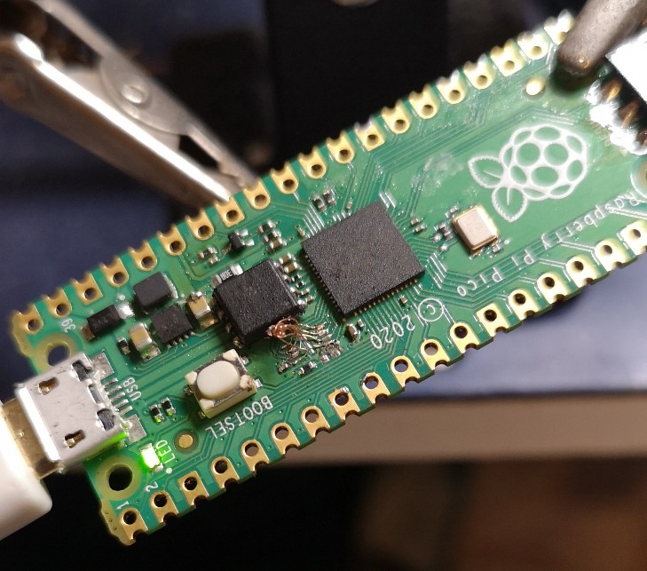
For regular debug output from the program I connected a Raspberry Pi Pico serial port to an FTDI USB Serial TTL adapter connected back to my PC – see the image below.
At some point I’ll revisit this setup. First, it’s now possible to printf to a virtual USB serial port, so that frees up that Raspberry Pi Pico serial port. Secondly, I need to get that VSCode integration working.
Tracker code
My Raspberry Pi and Arduino tracker programs work slightly differently. On the Raspberry Pi, to separate the code for the different functions (GPS, radio, sensors etc) I use a separate thread for each. That allows for example a new packet to be sent to the radio transmitter without delay, even if a slow operation is running concurrently elsewhere.
On the Arduino, with no threads available, the code is still split into separate modules but each one is coded to run quickly without waiting in a loop for a peripheral to respond. For example some temperature sensors can take a second or so to take a measurement, and it’s vital not to sit in a loop waiting for the result.
The C toolchain for Raspberry Pi Pico doesn’t, by default, support threaded code unfortunately. Rather than rebuild it with support added, I opted for the approach I use with Arduino. So the main code starts with initialising each module individually, and then sits in a tight loop calling each module once per loop. It’s then up to each module to return control swiftly so that the loop keeps running quickly and no module is kept waiting for long.
Code modules
The GPS code uses a serial port to receive NMEA data from the GPS. NMEA is the standard ASCII protocol used by pretty much every GPS module that exists, and includes the current date, time, latitude, longitude, altitude and other data. All we need to do is confirm that the data is valid, then read and store these key values. The other important function is to ensure that the GPS module is in the correct “flight mode” so that it works at high altitude – without this then it will stop providing new positions about 18km altitude.
The LoRa radio code checks to see when the module is not transmitting, then builds a new telemetry message containing the above GPS data plus the name of the balloon, any other sensor data, and the landing prediction (see later).
This message is passed to the LoRa chip via SPI, then the chip switches on its radio and modulates the radio signal with the telemetry data. Once the message has been sent then the chip switches on its DIO0 output which is connected to the Raspberry Pi Pico so it knows when it can send another message.
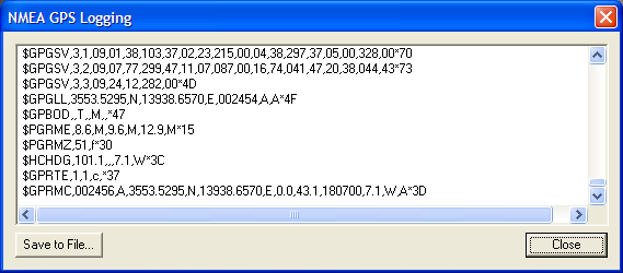
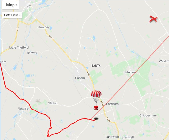
All messages are received on the ground (in this case by a Pi LoRa receiver) and then uploaded to an internet database that in turn drives a live Google map (see image below).
Sensors
Usefully for balloon trackers, the Raspberry Pi Pico can be powered directly from battery via an on-board buck-boost converter.
The input voltage connects through a potential divider to an analog sense input (ADC3) to allow for easy measurement of the battery voltage. Note that the ADC reference voltage is the 3.3V rail, which is noisy especially when used to power external devices such as the GPS and LoRa both of which have rather spiky power consumption requirements, so the code averages out many measurements.
An alternative would be to add a precise reference voltage to the ADC but I went for the zero cost software option.
The board temperature can also be measured, this time using ADC4. That’s less useful though for a tracker than an external temperature measurement, so I added a BME280 device for that. The Raspberry Pi Pico samples include code for the BME connected via SPI, but I chose I2C so I needed to replace the SPI calls with I2C calls. Pretty easy. The BME280 returns pressure – probably the most interesting environmental measurement for a balloon tracker – and humidity too.
Landing prediction
So far, everything I’ve done could also be done on a basic AVR chip e.g. the Arduino Mini Pro, with some spare room. However, one very useful extra is to add a prediction of the landing point.
We use online flight prediction prior to launch, to determine roughly where the balloon will land (within a few miles) so we know it’s safe to launch without landing near a city for example. This uses a global wind prediction database plus some flight parameters (e.g. ascent rate and burst altitude) to predict the path of the balloon from launch to landing. It can be very accurate if those parameters are followed through on the flight itself.
Of course the actual flight never quite follows the plan – for example the launch might be later than planned, and in changing wind conditions that itself can move the landing point by miles. So it’s useful to have a live prediction during that flight, and indeed we have that, using the same wind database.
However, since it’s online, and 3G/4G can be patchy when chasing a balloon, it’s useful to have an independent landing prediction. This can be done in the tracker itself, by storing the wind speed and direction (deduced from GPS positions) on the way up, measuring the descent rate after burst, applying that to an atmospheric density model to plot the future descent rate to the ground, and then calculating the effect of the wind during descent and finally producing a landing position.
Typical Arduino boards don’t have enough memory to store the measured wind data, but the Raspberry Pi Pico has more than enough. I ported my existing code which:
During ascent, it splits the vertical range into 100 metres sections, into which it stores the latitude and longitude deltas as degrees per second.
Every few seconds, it runs a prediction of the landing position based on the current position, the data in that array, and an estimated descent profile that uses a simple atmospheric model plus default values for payload weight and parachute effectiveness.
During descent, the parachute effectiveness is measured, and the actual figure is used in the above calculation in (2).
Calculates the time it will spend within each 100m section of air, then multiplies that by the stored wind speed to calculate the horizontal distance and direction it is expected to travel in that section.
Adds all those sectional movements together, adds those to the current position, and produces the landing prediction.
Sends that position down to the ground with the rest of the telemetry.
Phew. Now we know pretty much everything about how balloon trackers work. Thanks Dave! Also, if you want to go on your own near-space flight, check out High Altitude Ballooning.
We’ve tried to make it as easy as possible for you to load your code onto your new Raspberry Pi Pico: press and hold the BOOTSEL button, plug your Pico into your computer, and it’ll mount as a mass storage volume. Then just drag and drop a UF2 file onto the board.
However, not everybody is keen to keep unplugging their micro USB cable every time they want to upload a UF2 onto the board. Don’t worry — there’s more than one way around that problem.
Raspberry Pi Pico with a reset button wired to the GND and RUN pins
Firstly, if you’re developing in MicroPython there isn’t any real need to unplug and replug Pico to write code. The only time you’ll need to do it is the initial upload of the MicroPython firmware, which comes as a UF2. From there on in, you’re talking to the board via the REPL and a serial connection, either in Thonny or some other editor.
However, if you’re developing using our C SDK, then to upload new code to your Pico you have to upload a new UF2. This means you’ll need to unplug and replug the board to put Pico into BOOTSEL mode each time you make a change in your code and want to test it.
No more unplugging with SWD?
The best way around this is to use SWD mode (see Chapter 5 of our C/C++ Getting Started book) to upload code using the debug port, instead of using mass storage (BOOTSEL) mode.
A Raspberry Pi 4 and Raspberry Pi Pico with UART and SWD ports connected together
This gets you debugger support, which is invaluable while developing, and involves adding just three more wires. Afterwards, you’ll never have to unplug your Pico again.
Keep on dragging and dropping
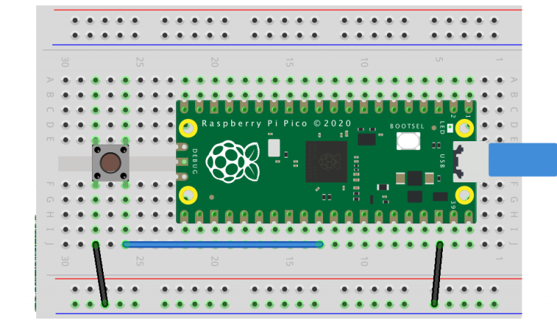
But if you want to stick with uploading by drag-and-drop, adding a reset button to your Raspberry Pi Pico is pretty easy.
Raspberry Pi Pico with a reset button wired to the GND and RUN pins
All you need to do is to wire the GND and RUN pins together and add an extra momentary contact button to your breadboard. Pushing the button will reset the board.
Then, instead of unplugging and replugging the USB cable when you want to load code onto Pico, you push and hold the RESET button, push the BOOTSEL button, release the RESET button, then release the BOOTSEL button.
Entering BOOTSEL mode without unplugging your Pico
If your board is in BOOTSEL mode and you want to start code you’ve already loaded running again, all you have to do now is briefly push the RESET button.
Leaving BOOTSEL mode without unplugging your Pico.
We’ve see some people use the 3V3_EN pin instead of the RUN pin. While it’ll work in a pinch, the problem with disabling 3.3V is that GPIOs that are driven from powered external devices will leak like crazy while 3.3V is disabled. There is even the possibility of damage to the chip. So it’s much better to use the RUN pin to make a reset button than the 3V3_EN pin.
What about the other button?
As an aside, if you want to break out the BOOTSEL button as well — perhaps you’re intending to bury your Pico inside an enclosure — you can use TP6 (that is, Test Point 6) on the rear of the board to do so. See Chapter 2 of the Pico Datasheet for details.
Where to find more help and information
Support for developing for Pico can be found on the Raspberry Pi forums. There is also an (unofficial) Discord server where a lot of people active in the new community seem to be hanging out. Feedback on the documentation should be posted as an issue to the pico-feedback repository on GitHub, or directly to the relevant repository it concerns.
All of the documentation, along with lots of other help and links, can be found on the same Getting Started page from which we grabbed our original UF2 file.
If you lose track of where that is in the future, you can always find it from your Pico: to access the page, just press and hold the BOOTSEL button on your Pico, plug it into your laptop or Raspberry Pi, then release the button. Go ahead and open the RPI-RP2 volume, and then click on the INDEX.HTM file.
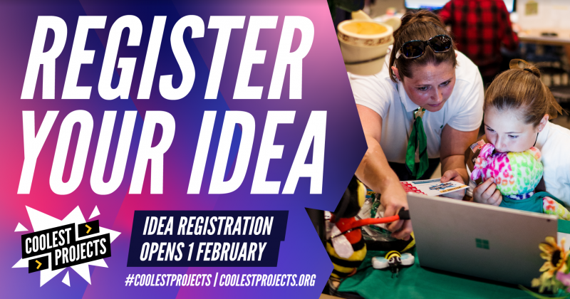
It’s official: idea registration is finally open for Coolest Project 2021!
Our Coolest Projects online showcase brings together a worldwide community of young people who make things with technology. Everyone up to age 18, wherever they are in the world, can register for Coolest Projects to become part of this community with their own tech creation! We welcome all ideas, all experience levels, and all kinds of projects.
So let all the young people in your family, school, or coding club know, because Coolest Projects is their chance to be part of something amazing this year!
Taking part is free, and projects will be displayed in the Coolest Projects online gallery for people all across the globe to see! And getting involved is super easy: young creators can start by registering their idea for a project now, leaving them plenty of time — until May — to build the project at home.
To celebrate the passion, effort, and creativity of all the tech creators, we will host a grand live-streamed finale event in June, where our fabulous, world-renowned judges will pick their favourites from among all the projects!
Coolest Projects is a powerful motivator for young people to develop skills in:
Idea generation
Project design and planning
Coding and technology
User testing and iteration
Presentation
…and they will have lots of fun, be inspired by their peers, and feel like they are part of a truly international community.
Let their imaginations run free!
Through the Coolest Projects online showcase, young people get the opportunity to explore their creativity and realise their tech ambitions! Whatever they come up with as a project idea, we want them to register so the Coolest Projects community can celebrate it.
Once their project ideas are registered, the young people can start creating their projects!
From the start of March, they will be able to complete their registration by adding the details of their project, including either a Scratch project link or a short video where they need to answer three important questions about their project. We’ll be offering online sessions to give them tips for their video and help them complete their showcase gallery entry.
Project registration closes on 3 May. But don’t worry if a project isn’t finished by then: we welcome works in progress just as much as completed creations!
We can’t wait to see the wonderful, imaginative things young tech creators in this global community are going to share with the world!
Sign up for the Coolest Projects newsletter to never miss the latest updates about our exciting online showcase, including the free online support sessions for participants.
The new Raspberry Pi Pico is very different from a traditional Raspberry Pi. Pico is a microcontroller, rather than a microcomputer. Unlike a Raspberry Pi it’s a platform you develop for, not a platform you develop on.
Blinking the onboard LED
But you still have choices if you want to develop for Pico, because there is both a C/C++ SDK and an official MicroPython port. Beyond that there are other options opening up, with a port of CircuitPython from Adafruit and the prospect of Arduino support, or even a Rust port.
Here I’m going to talk about how to get started with the C/C++ SDK, which lets you develop for Raspberry Pi Pico from your laptop or Raspberry Pi.
I’m going to assume you’re using a Raspberry Pi; after all, why wouldn’t you want to do that? But if you want to develop for Pico from your Windows or Mac laptop, you’ll find full instructions on how to do that in our Getting Started guide.
Blinking your first LED
When you’re writing software for hardware, the first program that gets run in a new programming environment is typically turning an LED on, off, and then on again. Learning how to blink an LED gets you halfway to anywhere. We’re going to go ahead and blink the onboard LED on Pico, which is connected to pin 25 of the RP2040 chip.
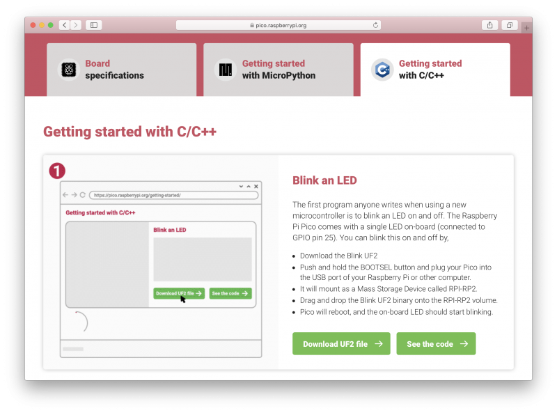
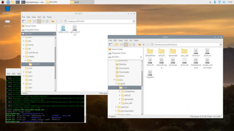
We’ve tried to make getting started with Raspberry Pi Pico as easy as possible. In fact, we’ve provided some pre-built binaries that you can just drag and drop onto your Raspberry Pi Pico to make sure everything is working even before you start writing your own code.
Go to the Getting Started page and click on the “Getting started with C/C++” tab, then the “Download UF2 file” button in the “Blink an LED” box.
A file called blink.uf2 will be downloaded to your computer. Go grab your Raspberry Pi Pico board and a micro USB cable. Plug the cable into your Raspberry Pi or laptop, then press and hold the BOOTSEL button on your Pico while you plug the other end of the micro USB cable into the board. Then release the button after the board is plugged in.
A disk volume called RPI-RP2 should pop up on your desktop. Double-click to open it, and then drag and drop the UF2 file into it. The volume will automatically unmount and the light on your board should start blinking.
Blinking an LED
Congratulations! You’ve just put code onto your Raspberry Pi Pico for the first time. Now we’ve made sure that we can successfully get a program onto the board, let’s take a step back and look at how we’d write that program in the first place.
Getting the SDK
Somewhat unsurprisingly, we’ve gone to a lot of trouble to make installing the tools you’ll need to develop for Pico as easy as possible on a Raspberry Pi. We’re hoping to make things easier still in the future, but you should be able to install everything you need by running a setup script.
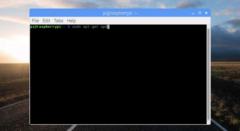
However, before we do anything, the first thing you’ll need to do is make sure your operating system is up to date.
The script will do a lot of things behind the scenes to configure your Raspberry Pi for development, including installing the C/C++ command line toolchain and Visual Studio Code. Once it has run, you will need to reboot your Raspberry Pi.
The script has been tested and is known to work from a clean, up-to-date installation of Raspberry Pi OS. However, full instructions, along with instructions for manual installation of the toolchain if you prefer to do that, can be found in the “Getting Started” guide.
Once your Raspberry Pi has rebooted we can get started writing code.
Writing code for your Pico
There is a large amount of example code for Pico, and one of the things that the setup script will have done is to download the examples and build both the Blink and “Hello World” examples to verify that your toolchain is working.
But we’re going to go ahead and write our own.
We’re going to be working in the ~/pico directory created by the setup script, and the first thing we need to do is to create a directory to house our project.
If all goes well you should see a whole bunch of messages flash past in your Terminal window and a number of files will be generated in the build/ directory, including one called blink.uf2.
Just as we did before with the UF2 file we downloaded from the Getting Started page, we can now drag and drop this file on to our Pico.
Unplug the cable from your Pico, then press and hold the BOOTSEL button on your Pico and plug it back in. Then release the button after the board is plugged in.
The new blink.uf2 binary can be dragged and dropped on to our Pico
The RPI-RP2 disk volume should pop up on your desktop again. Double-click to open it, then open a file viewer in the pico/blink/build/ directory and drag and drop the UF2 file you’ll find there on to the RPI-RP2 volume. It will automatically unmount, and the light on your board should start blinking. But this time it will blink a little bit differently from before.
Try playing around with the sleep_ms( ) lines in our code to vary how much time there is between blinks. You could even take a peek at one of the examples, which shows you how to blink the onboard LED in Morse code.
Using Picotool
One way to convince yourself that the program running on your Pico is the one we just built is to use something called picotool. Picotool is a command line utility installed by the setup script that is a Swiss Army knife for all things Pico.
Go ahead and unplug your Pico from your Raspberry Pi, press and hold the BOOTSEL button, and plug it back in. Then run picotool.
You’ll see lots of information about the program currently on your Pico. Then if you want to start it blinking again, just unplug and replug Pico to leave BOOTSEL mode and start your program running once more.
Picotool can do a lot more than this, and you’ll find more information about it in Appendix B of the “Getting Started” guide.
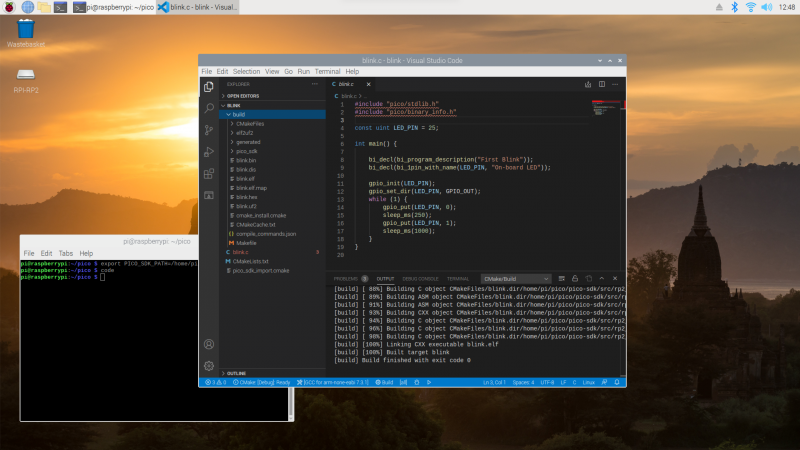
Using Visual Studio Code
So far we’ve been building our Pico projects from the command line, but the setup script also installed and configured Visual Studio Code, and we can build the exact same CMake-based project in the Visual Studio Code environment. You can open it as below:
Chapter 6 of the Getting Started guide has full details of how to load and compile a Pico project inside Visual Studio Code. If you’re used to Visual Studio Code, you might be able to make your way from here without much extra help, as the setup script has done most of the heavy lifting for you in configuring the IDE.
What’s left is to open the pico/blink folder and allow the CMake Tools extension to configure the project. After selecting arm-none-eabi as your compiler, just hit the “Build’ button in the blue bottom bar.
Building our blink project inside Visual Studio Code
While we recommend and support Visual Studio Code as the development environment of choice for developing for Pico — it works cross-platform under Linux, Windows, and macOS and has good plugin support for debugging — you can also take a look at Chapter 9 of the Getting Started guide. There we talk about how to use both Eclipse and CLion to develop for Pico, and if you’re more used to those environments you should be able to get up and running in either without much trouble.
Where now?
If you’ve got this far, you’ve built and deployed your very first C program to your Raspberry Pi Pico. Well done! The next step is probably going to be saying “Hello World!” over serial back to your Raspberry Pi.
From here, you probably want to sit down and read the Getting Started guide I’ve mentioned throughout the article, especially if you want to make use of SWD debugging, which is discussed at length in the guide. Beyond that I’d point you to the book on the C/C++ SDK which has the API-level documentation, as well as a high-level discussion of the design of the SDK.
Support for developing for Pico can be found on the Raspberry Pi forums. There is also an (unofficial) Discord server where a lot of people active in the new community seem to be hanging out. Feedback on the documentation should be posted as an Issue to the pico-feedback repository on Github, or directly to the relevant repository it concerns.
All of the documentation, along with lots of other help and links, can be found on the same Getting Started page from which we grabbed our original UF2 file.
If you lose track of where that is in the future, you can always find it from your Pico: to access the page, just press and hold the BOOTSEL button on your Pico, plug it into your laptop or Raspberry Pi, then release the button. Go ahead and open the RPI-RP2 volume, and then click on the INDEX.HTM file.
“It’s a flexible product and platform,” says Nick Francis, Senior Engineering Manager at Raspberry Pi, when discussing the work the Application-Specific Integrated Circuit (ASIC) team put into designing RP2040, the microcontroller at the heart of Raspberry Pi Pico.
It would have been easy to have said, well, let’s do a purely educational microcontroller “quite low-level, quite limited performance,” he tells us. “But we’ve done the high-performance thing without forgetting about making it easy to use for beginners. To do that at this price point is really good.”
James Adams, Chief Operating Officer
Nick Francis, Senior Engineering Manager
“I think we’ve done a pretty good job,” agrees James Adams, Chief Operating Officer at Raspberry Pi. “We’ve obviously tossed around a lot of different ideas about what we could include along the way, and we’ve iterated quite a lot and got down to a good set of features.”
A board and chip
“The idea is it’s [Pico] a component in itself,” says James. “The intent was to expose as many of the I/O (input/output) pins for users as possible, and expose them in the DIP-like (Dual Inline Package) form factor, so you can use Raspberry Pi Pico as you might use an old 40-pin DIP chip. Now, Pico is 2.54 millimetres or 0.1 inch pitch wider than a ‘standard’ 40-pin DIP, so not exactly the same, but still very similar.
“After the first prototype, I changed the pins to be castellated so you can solder it down as a module, without needing to put any headers in. Which is, yes, another nod to using it as a component.”
Getting the price right
“One of the things that we’re very excited about is the price,” says James. “We’re able to make these available cheap as chips – for less than the price of a cup of coffee.”
“It’s extremely low-cost,” Nick agrees. “One of the driving requirements right at the start was to build a very low-cost chip, but which also had good performance. Typically, you’d expect a microcontroller with this specification to be more expensive, or one at this price to have a lower specification. We tried to push the performance and keep the cost down.”
“We’re able to make these available cheap as chips.”
James Adams
Raspberry Pi Pico also fits nicely into the Raspberry Pi ecosystem: “Most people are doing a lot of the software development for this, the SDK (software development kit) and all the rest of it, on Raspberry Pi 4 or Raspberry Pi 400,” James explains. “That’s our primary platform of choice. Of course, we’ll make it work on everything else as well. I would hope that it will be as easy to use as any other microcontroller platform out there.”
Eben Upton on RP2040
“RP2040 is an exciting development for Raspberry Pi because it’s Raspberry Pi people making silicon,” says Eben Upton, CEO and co-founder of Raspberry Pi. “I don’t think other people bring their A-game to making microcontrollers; this team really brought its A-game. I think it’s just beautiful.
Is Pico really that small, or is Eben a giant?
“What does Raspberry Pi do? Well, we make products which are high performance, which are cost-effective, and which are implemented with insanely high levels of engineering attention to detail – and this is that. This is that ethos, in the microcontroller space. And that couldn’t have been done with anyone else’s silicon.”
Issue #102 of The MagPi Magazine is out NOW
Never want to miss an issue? Subscribe to The MagPi and we’ll deliver every issue straight to your door. Also, if you’re a new subscriber and get the 12-month subscription, you’ll get a completely free Raspberry Pi Zero bundle with a Raspberry Pi Zero W and accessories.
Look at our lovely friends over at This is not Rocket Science (TiNRS) – they’ve wasted no time at all in jumping in with our new chips. In this guest post, Stijn of TiNRS shares their fishily musical application of our new toy.
The new RP2040 chip by Raspberry Pi is amazing. When we got our hands on this beautiful little thing, we did what we always do with new chips and slapped on a Goldfish, our favourite acid bassline synthesiser (we make fish and chips, hahahaha).
TiNRS took to Instagram to explain more about the 18 year old fish synthesiser project
While benchmarking the performance by copy/pasting instances of our entire Goldfish in search of the chip’s limits, we suddenly found ourselves with a polyphonic synth. We have since rewritten these multiple instances into a 16-voice Poly-Goldfish with 4 oscillators per voice. To celebrate we designed a PCB and brightly coloured frontpanel to give this new Goldfish some dedicated controls.
Bring-up was trivial due to the amazing documentation and the extremely flexible PIO-blocks. RP2040 is a dream to work with. Childlike giddiness ensued while lying on the carpet and programming in VSCode on a Raspberry Pi 400 talking directly to the RP2040. This is the way to release a chip into the world: with fantastic documentation, an open toolchain and plenty of examples of how to use everything.
PCB and brightly coloured front panel
Once these chips hit general availability we will probably share some designs on our Github. This chip is now part of our go-to set of tools to make cool stuff and will very bloody likely be inside our next three modules.
It fits perfectly in our Open Source attitude. Because of the easy, high quality, multi-platform, free and even beginner-friendly toolchain they have built around this chip, we can expand the accessibility to the insides of our designs. With these chips it is way easier for us to have you do things like adding your own algorithms, building extra modes or creating personal effects. We can lean on the quality of the Raspberry Pi platform and this amazing chip.
TiNRS approves.
Keep an eye on the TiNR blog for more adventures in technology. You can also find them on Twitter @rocket_not and on Instagram.
So, you’ve got a brand new Raspberry Pi Pico and want to know how to get started with this tiny but powerful microcontroller? We’ve got just the book for you.
Beginner-friendly
In Get Started with MicroPython on Raspberry Pi Pico, you’ll learn how to use the beginner-friendly language MicroPython to write programs and connect hardware to make your Raspberry Pi Pico interact with the world around it. Using these skills, you can create your own electro-mechanical projects, whether for fun or to make your life easier.
After taking you on a guided tour of Pico, the books shows you how to get it up and running with a step-by-step illustrated guide to soldering pin headers to the board and installing the MicroPython firmware via a computer.
Programming basics
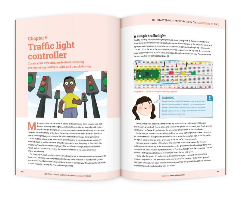
Next, we take you through the basics of programming in MicroPython, a Python-based programming language developed specifically for microcontrollers such as Pico. From there, we explore the wonderful world of physical computing and connect a variety of electronic components to Pico using a breadboard. Controlling LEDs and reading input from push buttons, you’ll start by creating a pedestrian crossing simulation, before moving on to projects such as a reaction game, burglar alarm, temperature gauge, and data logger.
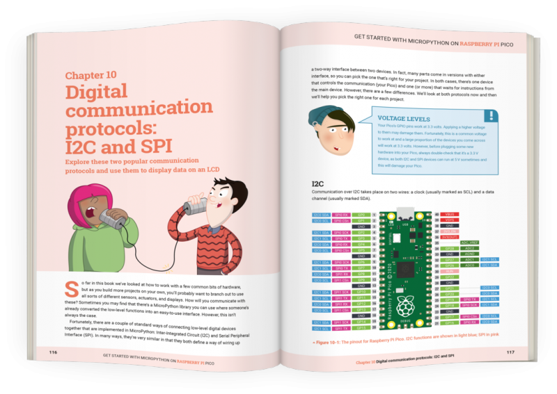
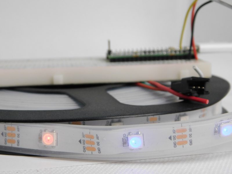
Raspberry Pi Pico also supports the I2C and SPI protocols for communicating with devices, which we explore by connecting it up to an LCD display. You can even use MicroPython to take advantage of one of Pico’s most powerful features, Programmable I/O (PIO), which we explore by controlling NeoPixel LED strips.
Get your copy today!
You can buy Get Started with MicroPython on Raspberry Pi Pico now from the Raspberry Pi Press online store. If you don’t need the lovely new book, with its new-book smell, in your hands in real life, you can download a PDF version for free (or a small voluntary contribution).
STOP PRESS: we’ve spotted an error in the first print run of the book, affecting the code examples in Chapters 4 to 7. We’re sorry! Fortunately it’s easy for readers to correct in their own code; see here for everything you need to know. We’ve already corrected this in the PDF version.
The best part of launching a new product is seeing the reaction of the Raspberry Pi community. When we released Raspberry Pi Pico into the world last Thursday, it didn’t take long for our curious, creative crew of hackers and tinkerers to share some brilliant videos, blogs and photos.
If you’ve spotted other cool stuff people have done with Raspberry Pi Pico, do comment with a link at the end of this post so we can check it out.
Graham Sanderson’s BBC Micro emulation
YouTube went wild for this Raspberry Pi Pico-powered BBC Micro and BBC Master emulation. Graham Sanderson‘s little bit of fun with our latest creation emulates the fine detail of the hardware required to get the best games and graphics demos to run.
He’s put together an entire playlist showing off the power of Raspberry Pi Pico, and it’s a retro gamer’s dream.
She has a good look around our launch blog post on camera too, unpacking some of the technical aspects of how Raspberry Pi Pico is powered, and also explaining why it’s so exciting that we’ve built this ourselves.
Jeff Geerling
Jeff Geerling has used his Pico for good, creating a baby-safe temperature monitor for his little one’s bedroom. In his video, he shows you around some of Raspberry Pi Pico’s “party tricks”, and includes the all-important build montage sequence.
If you prefer words to videos, Jeff has also put together a big ole blog post about our new microcontroller board.
Brian Corteil
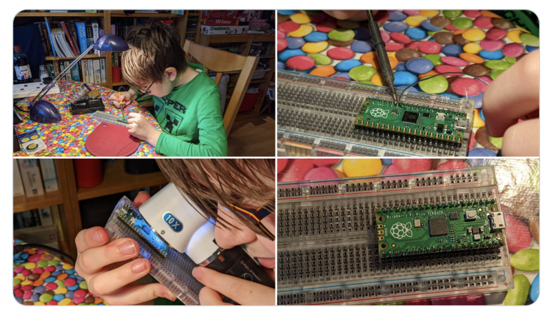
Brian Corteil took to Twitter to share his eleven-year-old’s pro soldering skills, proving that Raspberry Pi is for everyone, no matter how young, old, or inexperienced, or expert.
Extreme close-up!
Look at the finish on those pins!
16MB Pico modification
Daniel Green did what you were all thinking – desoldered the onboard 2MB QSPI flash chip and replaced it with a 16MB version. Say hello to the first Pico in the world with this special modification.
Eben himself!
On top of all the brilliant comments, projects, and guidance our community has already shared, Raspberry Pi CEO Eben Upton will be joining the Digital Making at Home crew on Wednesday to show you around Raspberry Pi Pico.
In the extra special Raspberry Pi Pico launch issue of HackSpace magazine, editor Ben Everard shows you how to get extra levels of brightness out of your LEDs with our new board.
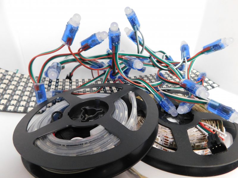
WS2812B LEDs, commonly known as NeoPixels, are cheap and widely available LEDs. They have red, green, and blue LEDs in a single package with a microcontroller that lets you control a whole string of them using just one pin on your microcontroller.
The three connections may be in a different order on your LED strip, so check the labels to make sure they’re connected correctly
However, they do have a couple of disadvantages:
1) The protocol needed to control them is timing-dependent and often has to be bit-banged.
2) Each colour has 8 bits, so has 255 levels of brightness. However, these aren’t gamma-corrected, so the low levels of brightness have large steps between them. For small projects, we often find ourselves only using the lower levels of brightness, so often only have 10 or 20 usable levels of brightness.
There will usually be wires already connected to your strip, but if you cut it, you’ll need to solder new wires on
We’re going to look at how two features of Pico help solve these problems. Firstly, Programmable I/O (PIO) lets us implement the control protocol on a state machine rather than the main processing cores. This means that we don’t have to dedicate any processor time to sending the data out. Secondly, having two cores means we can use one of the processing cores to dither the NeoPixels. This means shift them rapidly between different brightness levels to make pseudo-levels of brightness.
For example, if we wanted a brightness level halfway between levels 3 and 4, we’d flick the brightness back and forth between 3 and 4. If we can do this fast enough, our eyes blur this into a single brightness level and we don’t see the flicker. By varying the amount of time at levels 3 and 4, we can make many virtual levels of brightness. While one core is doing this, we still have a processing core completely free to manipulate the data we want to display.
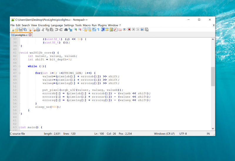
First, we’ll need a PIO program to communicate with the WS2812B LEDs. The Pico development team have provided an example PIO program to work with – you can see the full details here, but we’ll cover the essentials here. The PIO code is:
We looked at the PIO syntax in the main cover feature, but it’s basically an assembly language for the PIO state machine. The WS2812B protocol uses pulses at a rate of 800kHz, but the length of the pulse determines if a 1 or a 0 is being sent. This code uses jumps to move through the loop to set the timings depending on whether the bit (stored in the register x) is 0 or 1. The T1, T2, and T3 variables hold the timings, so are used to calculate the delays (with 1 taken off as the instruction itself takes one clock cycle). There’s also a section in the pio file that links the PIO code and the C code:
This line sets up the output shift register which holds each 32 bits of data before it’s moved bit by bit into the PIO state machine. The parameters are the config (that we’re setting up and will use to initialise the state machine); a Boolean value for shifting right or left (false being left); and a Boolean value for autopull which we have set to true. This means that whenever the output shift register falls below a certain threshold (set in the next parameter), the PIO will automatically pull in the next 32 bits of data.
Using a text editor with programmer’s features such as syntax highlighting will make the job a lot easier
The final parameter is set using the expression rgbw ? 32 : 24. This means that if the variable rgbw is true, the value 32 is passed, otherwise 24 is passed. The rbgw variable is passed into this function when we create the PIO program from our C program and is used to specify whether we’re using an LED strip with four LEDs in each (using one red, one green, one blue, and one white) or three (red, green, and blue).
The PIO hardware works on 32-bit words, so each chunk of data we write with the values we want to send to the LEDs has to be 32 bits long. However, if we’re using RGB LED strips, we actually want to work in 24-bit lengths. By setting autopull to 24, we still pull in 32 bits each time, but once 24 bits have been read, another 32 bits are pulled in which overwrite the remaining 8 bits.
Each state machine has two four-word FIFOs attached to it. These can be used for one going in and one coming out. However, as we only have data going into our state machine, we can join them together to form a single eight-word FIFO using the above line. This gives us a small buffer of time to write data to in order to avoid the state machine running out of data and execution stalling. The following three lines are used to set the speed the state machine runs at:
The WS2812B protocol demands that data is sent out at a rate of 800kHz. However, each bit of data requires a number of state machine cycles. In this case, they’re defined in the variables T1, T2, and T3. If you look back at the original PIO program, you’ll see that these are used in the delays (always with 1 taken off the value because the initial instruction takes one cycle before the delay kicks in). Every loop of the PIO program will take T1 + T2 + T3 cycles. We use these values to calculate the speed we want the state machine to run at, and from there we can work out the divider we need to slow the system clock down to the right speed for the state machine. The final two lines just initialise and enable the state machine.
The main processor
That’s the code that’s running on the state machine, so let’s now look at the code that’s running on our main processor cores. The full code is on github. Let’s first look at the code running on the second core (we’ll look at how to start this code running shortly), as this controls the light levels of the LEDs.
We start by defining a virtual bit depth. This is how many bits per pixel you can use. Our code will then attempt to create the necessary additional brightness levels. It will run as fast as it can drive the LED strip, but if you try to do too many brightness levels, you’ll start to notice flickering.
We found twelve to be about the best with strings up to around 100 LEDs, but you can experiment with others. Our code works with two arrays – pixels which holds the values that we want to display, and errors which holds the error in what we’ve displayed so far (there are three of each for the different colour channels).
If you just want to see this in action, you can download the UF2 file from hsmag.cc/orfgBD and flash it straight to your Pico
To explain that latter point, let’s take a look at the algorithm for determining how to light the LED. We borrowed this from the source code of Fadecandy by Micah Scott, but it’s a well-used algorithm for calculating error rates. We have an outer while loop that just keeps pushing out data to the LEDs as fast as possible. We don’t care about precise timings and just want as much speed as possible. We then go through each pixel.
The corresponding item in the errors array holds the cumulative amount our LED has been underlit so far compared to what we want it to be. Initially, this will be zero, but with each loop (if there’s a difference between what we want to light the LED and what we can light the LED) this error value will increase. These two numbers (the closest light level and the error) added together give the brightness at the pseudo-level, so we need to bit-shift this by the difference between our virtual level and the 8-bit brightness levels that are available.
This gives us the value for this pixel which we write out. We then need to calculate the new error level. Let’s take a look at what this means in practice. Suppose we want a brightness level halfway between 1 and 2 in the 8-bit levels. To simplify things, we’ll use nine virtual bits. 1 and 2 in 8-bit is 2 and 4 in 9 bits (adding an extra 0 to the end multiplies everything by a power of 2), so halfway between these two is a 9-bit value of 3 (or 11 in binary, which we’ll use from now on).
In the first iteration of our loop, pixels is 11, errors is 0, and shift is 1.
So this time, the brightness level of 10 (in binary, or 2 in base 10) is written out. This time, the errors go back to 0, so we’re in the same position as at the start of the first loop. In this case, the LED will flick between the two brightness levels each loop so you’ll have a brightness half way between the two.
Using this simple algorithm, we can experiment with different virtual bit-depths. The algorithm will always handle the calculations for us, but we just have to see what creates the most pleasing visual effect for the eye. The larger the virtual bit depth, the more potential iterations you have to go through before the error accumulates enough to create a correction, so the more likely you are to see flicker. The biggest blocker to increasing the virtual bit depth is the sleep_us(400). This is needed to reset the LED strip.
NeoPixels come in many different shapes and sizes
Essentially, we throw out bits at 800kHz, and each block of 24 bits is sent, in turn, to the next LED. However, once there’s a long enough pause, everything resets and it goes back to the first LED. How big that pause is can vary. The truth is that a huge proportion of WS2812B LEDs are clones rather than official parts – and even for official parts, the length of the pause needed to reset has changed over the years.
400 microseconds is conservative and should work, but you may be able to get away with less (possibly even as low as 50 microseconds for some LEDs). The urgb_u32 method simply amalgamates the red, blue, and green values into a single 32-bit string (well, a 24-bit string that’s held inside a 32-bit string), and put_pixel sends this to the state machine. The bit shift there is to make sure the data is in the right place so the state machine reads the correct 24 bits from the output shift register.
Getting it running
We’ve now dealt with all the mechanics of the code. The only bit left is to stitch it all together.
The method ws2812_program_init calls the method created in the PIO program to set everything up. To launch the algorithm creating the virtual bit-depth, we just have to use multicore_launch_core1 to set a function running on the other core. Once that’s done, whatever we put in the pixels array will be reflected as accurately as possible in the WS2812B LEDs. In this case, we simply fade it in and out, but you could do any animation you like.
Get a free Raspberry Pi Pico
Would you like a free Raspberry Pi Pico? Subscribe to HackSpace magazine via your preferred option here, and you’ll receive your new microcontroller in the mail before the next issue arrives.
Today, we’re launching our first microcontroller-class product: Raspberry Pi Pico. Priced at just $4, it is built on RP2040, a brand-new chip developed right here at Raspberry Pi. Whether you’re looking for a standalone board for deep-embedded development or a companion to your Raspberry Pi computer, or you’re taking your first steps with a microcontroller, this is the board for you.
You can buy your Raspberry Pi Pico today online from one of our Approved Resellers. Or head to your local newsagent, where every copy of this month’s HackSpace magazine comes with a free Pico, as well as plenty of guides and tutorials to help you get started with it. If coronavirus restrictions mean that you can’t get to your newsagent right now, you can grab a subscription and get Pico delivered to your door.
Oops!… We Did It Again
Microcomputers and microcontrollers
Many of our favourite projects, from cucumber sorters to high altitude balloons, connect Raspberry Pi to the physical world: software running on the Raspberry Pi reads sensors, performs computations, talks to the network, and drives actuators. This ability to bridge the worlds of software and hardware has contributed to the enduring popularity of Raspberry Pi computers, with over 37 million units sold to date.
But there are limits: even in its lowest power mode a Raspberry Pi Zero will consume on the order of 100 milliwatts; Raspberry Pi on its own does not support analogue input; and while it is possible to run “bare metal” software on a Raspberry Pi, software running under a general-purpose operating system like Linux is not well suited to low-latency control of individual I/O pins.
Many hobbyist and industrial applications pair a Raspberry Pi with a microcontroller. The Raspberry Pi takes care of heavyweight computation, network access, and storage, while the microcontroller handles analogue input and low-latency I/O and, sometimes, provides a very low-power standby mode.
Until now, we’ve not been able to figure out a way to make a compelling microcontroller-class product of our own. To make the product we really wanted to make, first we had to learn to make our own chips.
Raspberry Si
It seems like every fruit company is making its own silicon these days, and we’re no exception. RP2040 builds on the lessons we’ve learned from using other microcontrollers in our products, from the Sense HAT to Raspberry Pi 400. It’s the result of many years of hard work by our in-house chip team.
We had three principal design goals for RP2040: high performance, particularly for integer workloads; flexible I/O, to allow us to talk to almost any external device; and of course, low cost, to eliminate barriers to entry. We ended up with an incredibly powerful little chip, cramming all this into a 7 × 7 mm QFN-56 package containing just two square millimetres of 40 nm silicon. RP2040 has:
Dual-core Arm Cortex-M0+ @ 133MHz
264KB (remember kilobytes?) of on-chip RAM
Support for up to 16MB of off-chip Flash memory via dedicated QSPI bus
DMA controller
Interpolator and integer divider peripherals
30 GPIO pins, 4 of which can be used as analogue inputs
1 × USB 1.1 controller and PHY, with host and device support
8 × Raspberry Pi Programmable I/O (PIO) state machines
USB mass-storage boot mode with UF2 support, for drag-and-drop programming
And this isn’t just a powerful chip: it’s designed to help you bring every last drop of that power to bear. With six independent banks of RAM, and a fully connected switch at the heart of its bus fabric, you can easily arrange for the cores and DMA engines to run in parallel without contention.
For power users, we provide a complete C SDK, a GCC-based toolchain, and Visual Studio Code integration.
As Cortex-M0+ lacks a floating-point unit, we have commissioned optimised floating-point functions from Mark Owen, author of the popular Qfplib libraries; these are substantially faster than their GCC library equivalents, and are licensed for use on any RP2040-based product.
With two fast cores and and a large amount of on-chip RAM, RP2040 is a great platform for machine learning applications. You can find Pete Warden’s port of Google’s TensorFlow Lite framework here. Look out for more machine learning content over the coming months.
For beginners, and other users who prefer high-level languages, we’ve worked with Damien George, creator of MicroPython, to build a polished port for RP2040; it exposes all of the chip’s hardware features, including our innovative PIO subsystem. And our friend Aivar Annamaa has added RP2040 MicroPython support to the popular Thonny IDE.
Raspberry Pi Pico
Raspberry Pi Pico is designed as our low-cost breakout board for RP2040. It pairs RP2040 with 2MB of Flash memory, and a power supply chip supporting input voltages from 1.8-5.5V. This allows you to power your Pico from a wide variety of sources, including two or three AA cells in series, or a single lithium-ion cell.
Pico provides a single push button, which can be used to enter USB mass-storage mode at boot time and also as a general input, and a single LED. It exposes 26 of the 30 GPIO pins on RP2040, including three of the four analogue inputs, to 0.1”-pitch pads; you can solder headers to these pads or take advantage of their castellated edges to solder Pico directly to a carrier board. Volume customers will be able to buy pre-reeled Pico units: in fact we already supply Pico to our Approved Resellers in this format.
The Pico PCB layout was co-designed with the RP2040 silicon and package, and we’re really pleased with how it turned out: a two-layer PCB with a solid ground plane and a GPIO breakout that “just works”.
Reely good
Whether Raspberry Pi Pico is your first microcontroller or your fifty-first, we can’t wait to see what you do with it.
Raspberry Pi Pico documentation
Our ambition with RP2040 wasn’t just to produce the best chip, but to support that chip with the best documentation. Alasdair Allan, who joined us a year ago, has overseen a colossal effort on the part of the whole engineering team to document every aspect of the design, with simple, easy-to-understand examples to help you get the most out of your Raspberry Pi Pico.
You can find complete documentation for Raspberry Pi Pico, and for RP2040, its SDK and toolchain, here.
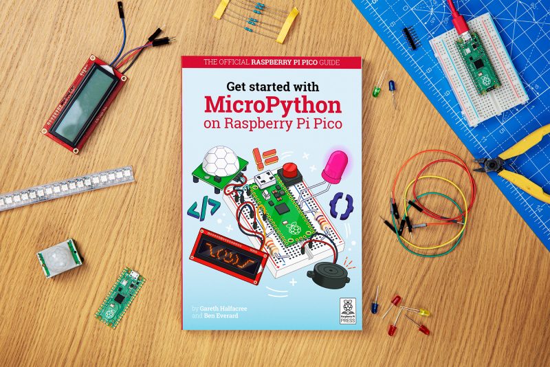
To help you get the most of your Pico, why not grab a copy of Get Started with MicroPython on Raspberry Pi Pico by Gareth Halfacree and our very own Ben Everard. It’s ideal for beginners who are new (or new-ish) to making with microcontrollers.
Our colleagues at the Raspberry Pi Foundation have also produced an educational project to help you get started with Raspberry Pi Pico. You can find it here.
Partners
Over the last couple of months, we’ve been working with our friends at Adafruit, Arduino, Pimoroni, and Sparkfun to create accessories for Raspberry Pi Pico, and a variety of other boards built on the RP2040 silicon platform. Here are just a few of the products that are available to buy or pre-order today.
Adafruit Feather RP 2040
RP2040 joins the hundreds of boards in the Feather ecosystem with the fully featured Feather RP 2040 board. The 2″ × 0.9″ dev board has USB C, Lipoly battery charging, 4MB of QSPI flash memory, a STEMMA QT I2C connector, and an optional SWD debug port. With plenty of GPIO for use with any FeatherWing, and hundreds of Qwiic/QT/Grove sensors that can plug and play, it’s the fast way to get started.
Feathery goodness
Adafruit ItsyBitsy RP 2040
Need a petite dev board for RP2040? The Itsy Bitsy RP 2040 is positively tiny, but it still has lots of GPIO, 4MB of QSPI flash, boot and reset buttons, a built-in RGB NeoPixel, and even a 5V output logic pin, so it’s perfect for NeoPixel projects!
Small is beautiful
Arduino Nano RP2040 Connect
Arduino joins the RP2040 family with one of its most popular formats: the Arduino Nano. The Arduino Nano RP2040 Connect combines the power of RP2040 with high-quality MEMS sensors (a 9-axis IMU and microphone), a highly efficient power section, a powerful WiFi/Bluetooth module, and the ECC608 crypto chip, enabling anybody to create secure IoT applications with this new microcontroller. The Arduino Nano RP2040 Connect will be available for pre-order in the next few weeks.
Get connected!
Pimoroni PicoSystem
PicoSystem is a tiny and delightful handheld game-making experience based on RP2040. It comes with a simple and fast software library, plus examples to make your mini-gaming dreams happen. Or just plug it into USB and drop the best creations from the Raspberry Pi-verse straight onto the flash drive.
Pixel-pushing pocket-sized playtime
Pimoroni Pico Explorer Base
Pico Explorer offers an embedded electronics environment for educators, engineers, and software people who want to learn hardware with less of the “hard” bit. It offers easy expansion and breakout along with a whole bunch of useful bits.
Go explore!
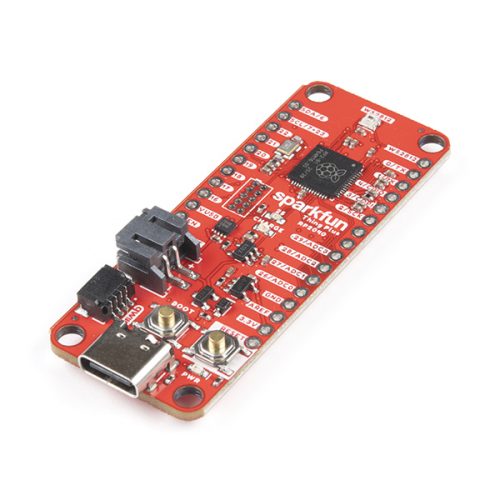
SparkFun Thing Plus – RP2040
The Thing Plus – RP2040 is a low-cost, high-performance board with flexible digital interfaces featuring Raspberry Pi’s RP2040 microcontroller. Within the Feather-compatible Thing Plus form factor with 18 GPIO pins, the board offers an SD card slot, 16MB (128Mbit) flash memory, a JST single-cell battery connector (with a charging circuit and fuel gauge sensor), an addressable WS2812 RGB LED, JTAG PTH pins, mounting holes, and a Qwiic connector to add devices from SparkFun’s quick-connect I2C ecosystem.
Thing One, or Thing Two?
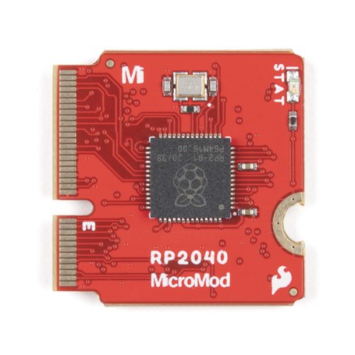
SparkFun MicroMod RP2040 Processor
The MicroMod RP2040 Processor Board is part of SparkFun’s MicroMod modular interface system. The MicroMod M.2 connector makes it easy to connect your RP2040 Processor Board with the MicroMod carrier board that gives you the inputs and outputs you need for your project.
The Mighty Micro
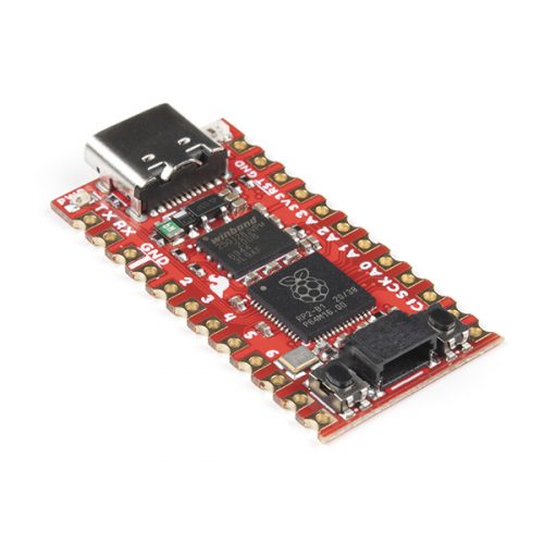
SparkFun Pro Micro – RP2040
The Pro Micro RP2040 harnesses the capability of RP2040 on a compact development board with the USB functionality that is the hallmark of all SparkFun’s Pro Micro boards. It has a WS2812B addressable LED, boot button, reset button, Qwiic connector, USB-C, and castellated pads.
Go Pro
Credits
It’s fair to say we’ve taken the long road to creating Raspberry Pi Pico. Chip development is a complicated business, drawing on the talents of many different people. Here’s an incomplete list of those who have contributed to the RP2040 and Raspberry Pi Pico projects:
Dave Akerman, Sam Alder, Alasdair Allan, Aivar Annamaa, Jonathan Bell, Mike Buffham, Dom Cobley, Steve Cook, Phil Daniell, Russell Davis, Phil Elwell, Ben Everard, Andras Ferencz, Nick Francis, Liam Fraser, Damien George, Richard Gordon, F Trevor Gowen, Gareth Halfacree, David Henly, Kevin Hill, Nick Hollinghurst, Gordon Hollingworth, James Hughes, Tammy Julyan, Jason Julyan, Phil King, Stijn Kuipers, Lestin Liu, Simon Long, Roy Longbottom, Ian Macaulay, Terry Mackown, Jon Matthews, Nellie McKesson, Rod Oldfield, Mark Owen, Mike Parker, David Plowman, Dominic Plunkett, Graham Sanderson, Andrew Scheller, Serge Schneider, Nathan Seidle, Vinaya Puthur Sekar, Mark Sherlock, Martin Sperl, Mike Stimson, Ha Thach, Roger Thornton, Jonathan Welch, Simon West, Jack Willis, Luke Wren, David Wright.
We’d also like to thank our friends at Sony Pencoed and Sony Inazawa, Microtest, and IMEC for their help in bringing these projects to fruition.
In this blog post, I’ll discuss the first research seminar in our six-part series about diversity and inclusion. Let’s start by defining our terms. Diversity is any dimension that can be used to differentiate groups and people from one another. This might be, for example, age, gender, socio-economic status, disability, ethnicity, religion, nationality, or sexuality. The aim of inclusion is to embrace all people irrespective of difference.
It’s vital that we are inclusive in computing education, because we need to ensure that everyone can access and learn the empowering and enabling technical skills they need to support all aspects of their lives.
We kicked off the series with a seminar from Dr Peter Kemp and Dr Billy Wong focused on computing education in England’s schools post-14. Peter is a Lecturer in Computing Education at King’s College London, where he leads on initial teacher education in computing. His research areas are digital creativity and digital equity. Billy is an Associate Professor at the Institute of Education, University of Reading. His areas of research are educational identities and inequalities, especially in the context of higher education and STEM education.
Dr Peter Kemp
Dr Billy Wong
Computing in England’s schools
Peter began the seminar with a comprehensive look at the history of curriculum change in Computing in England. This was very useful given our very international audience for these seminars, and I will summarise it below. (If you’d like more detail, you can look over the slides from the seminar. Note that these changes refer to England only, as education in the UK is devolved, and England, Northern Ireland, Scotland, and Wales each has a different education system.)
In 2014, England switched from mandatory ICT (Information and Communication Technology) to mandatory Computing (encompassing information technology, computer science, and digital literacy). This shift was complemented by a change in the qualifications for students aged 14–16 and 16–18, where the primary qualifications are GCSEs and A levels respectively:
At GCSE, there has been a transition from GCSE ICT to GCSE Computer Science over the last five years, with GCSE ICT being discontinued in 2017
At A level before 2014, ICT and Computing were on offer as two separate A levels; now there is only one, A level Computer Science
One of the issues is that in the English education system, there is a narrowing of the curriculum at age 14: students have to choose between Computer Science and other subjects such as Geography, History, Religious Studies, Drama, Music, etc. This means that those students that choose not to take a GCSE Computer Science (CS) may find that their digital education is thereby curtailed from then onwards. Peter’s and Billy’s view is that having a more specialist subject offer for age 14+ (Computer Science as opposed to ICT) means that fewer students take it, and they showed evidence of this from qualifications data. The number of students taking CS at GCSE has risen considerably since its introduction, but it’s not yet at the level of GCSE ICT uptake.
GCSE computer science and equity
Only 64% of schools in England offer GCSE Computer Science, meaning that just 81% of students have the opportunity to take the subject (some schools also add selection criteria). A higher percentage (90%) of selective grammar schools offer GCSE CS than do comprehensive schools (80%) or independent schools (39%). Peter suggested that this was making Computer Science a “little more elitist” as a subject.
Peter analysed data from England’s National Pupil Database (NPD) to thoroughly investigate the uptake of Computer Science post-14 with respect to the diversity of entrants.
He found that the gender gap for GCSE CS uptake is greater than it was for GCSE ICT. Now girls make up 22% of the cohort for GCSE CS (2020 data), whereas for the ICT qualification (2017 data), 43% of students were female.
Peter’s analysis showed that there is also a lower representation of black students and of students from socio-economically disadvantaged backgrounds in the cohort for GCSE CS. In contrast, students with Chinese ancestry are proportionally more highly represented in the cohort.
Another part of Peter’s analysis related gender data to the Income Deprivation Affecting Children Index (IDACI), which is used as an indicator of the level of poverty in England’s local authority districts. In the graphs below, a higher IDACI decile means more deprivation in an area. Relating gender data of GCSE CS uptake against the IDACI shows that:
Girls from more deprived areas are more likely to take up GCSE CS than girls from less deprived areas are
The opposite is true for boys
Peter covered much more data in the seminar, so do watch the video recording (below) if you want to learn more.
Peter’s analysis shows a lack of equity (i.e. equality of outcome in the form of proportional representation) in uptake of GCSE CS after age 14. It is also important to recognise, however, that England does mandate — not simply provide or offer — Computing for all pupils at both primary and secondary levels; making a subject mandatory is the only way to ensure that we do give access to all pupils.
What can we do about the lack of equity?
Billy presented some of the potential reasons for why some groups of young people are not fully represented in GCSE Computer Science:
There are many stereotypes surrounding the image of ‘the computer scientist’, and young people may not be able to identify with the perception they hold of ‘the computer scientist’
There is inequality in access to resources, as indicated by the research on science and STEM capital being carried out within the ASPIRES project
More research is needed to understand the subject choices young people make and their reasons for choosing as they do.
We also need to look at how the way we teach Computing to students aged 11 to 14 (and younger) affects whether they choose CS as a post-14 subject. Our next seminar revolves around equity-focused teaching practices, such as culturally relevant pedagogy or culturally responsive teaching, and how educators can use them in their CS learning environments.
Meanwhile, our own research project at the Raspberry Pi Foundation, Gender Balance in Computing, investigates particular approaches in school and non-formal learning and how they can impact on gender balance in Computer Science. For an overview of recent research around barriers to gender balance in school computing, look back on the research seminar by Katharine Childs from our team.
Peter and Billy themselves have recently been successful in obtaining funding for a research project to explore female computing performance and subject choice in English schools, a project they will be starting soon!
If you missed the seminar, watch recording here. You can also find Peter and Billy’s presentation slides on our seminars page.
Next up in our seminar series
In our next research seminar on Tuesday 2 February at 17:00–18:30 BST / 12:00–13:30 EDT / 9:00–10:30 PDT / 18:00–19:30 CEST, we’ll welcome Prof Tia Madkins (University of Texas at Austin), Dr Nicol R. Howard (University of Redlands), and Shomari Jones (Bellevue School District), who are going to talk to us about culturally responsive pedagogy and equity-focused teaching in K-12 Computer Science. To join this free online seminar, simply sign up with your name and email address.
Once you’ve signed up, we’ll email you the seminar meeting link and instructions for joining. If you attended Peter’s and Billy’s seminar, the link remains the same.
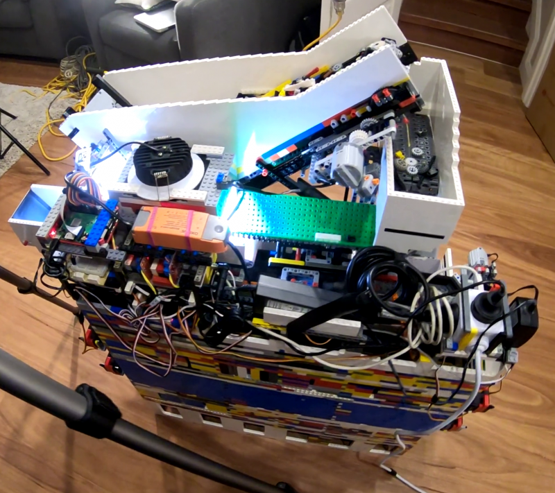
Raspberry Pi is at the heart of this AI–powered, automated sorting machine that is capable of recognising and sorting any LEGO brick.
And its maker Daniel West believes it to be the first of its kind in the world!
Best ever
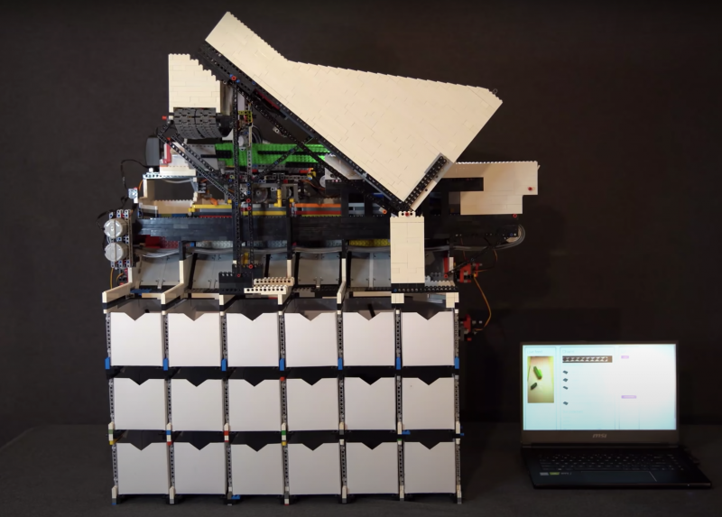
This mega-machine was two years in the making and is a LEGO creation itself, built from over 10,000 LEGO bricks.
A beast of 10,000 bricks
It can sort any LEGO brick you place in its input bucket into one of 18 output buckets, at the rate of one brick every two seconds.
While Daniel was inspired by previous LEGO sorters, his creation is a huge step up from them: it can recognise absolutely every LEGO brick ever created, even bricks it has never seen before. Hence the ‘universal’ in the name ‘universal LEGO sorting machine’.
9 servo motors (controlled through a servo multiplexer communicating with the Raspberry Pi on I2C)
6 LEGO motors (controlled through L298N motor controllers using digital I/O ports on Raspberry Pi)
Software
The artificial intelligence algorithm behind the LEGO sorting is a convolutional neural network, the go-to for image classification.
What makes Daniel’s project a ‘world first’ is that he trained his classifier using 3D model images of LEGO bricks, which is how the machine can classify absolutely any LEGO brick it’s faced with, even if it has never seen it in real life before.
We LOVE a thorough project video, and we love TWO of them even more
Daniel has made a whole extra video (above) explaining how the AI in this project works. He shouts out all the open source software he used to run the Raspberry Pi Camera Module and access 3D training images etc. at this point in the video.
LEGO brick separation
The vibration plate in action, feeding single parts into the scanner
Daniel needed the input bucket to carefully pick out a single LEGO brick from the mass he chucks in at once.
This is achieved with a primary and secondary belt slowly pushing parts onto a vibration plate. The vibration plate uses a super fast LEGO motor to shake the bricks around so they aren’t sitting on top of each other when they reach the scanner.
Scanning and sorting
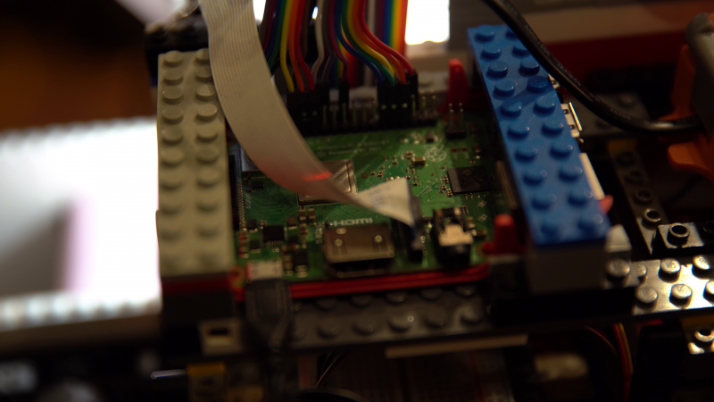
The underside of the beast
A Raspberry Pi Camera Module captures video of each brick, which Raspberry Pi 3 Model B+ then processes and wirelessly sends to a more powerful computer able to run the neural network that classifies the parts.
The classification decision is then sent back to the sorting machine so it can spit the brick, using a series of servo-controlled gates, into the right output bucket.
Extra-credit homework
In all its bricky beauty, with the 18 output buckets visible at the bottom
Daniel is such a boss maker that he wrote not one, but two further reading articles for those of you who want to deep-dive into this mega LEGO creation:
How to improve upon the standard burglar deterring method of leaving lights switched on? Dennis Mellican turned to Raspberry Pi for a much more effective solution. It actually proved too effective when a neighbour stopped by, but more on that in a bit.
Here you can see Dennis’s system in action scaring off a trespasser:
Good job, Raspberry Pi chatbots!
The burglar deterrent started out as Dennis’s regular home automation system. Not content with the current software offerings, and having worked in DevOps, Dennis decided to create his own solution. Enter Raspberry Pi (well, several of them).
Chatterboxes
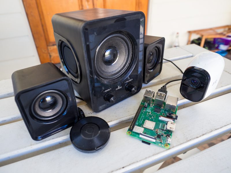
Dennis has multiple Raspberry Pi–powered devices dotted around his home, doing things such as turning on lights, powering up a garden sprinkler, and playing fake dog barks on wireless speakers. All these burglar deterrents work together and are run by a chat bot.
A simulation of the chatbots responding to Dennis’ commands
Each Raspberry Pi controls a single automated item in Dennis’s home. All the Raspberry Pis communicate with each other via Slack. Dennis issues commands if he, for example, wants lights to turn on while he is away, but the Raspberry Pis can also talk to each other when a trigger event occurs, such as when a motion sensor is tripped.
Smart sound
Speaker, Google Chromecast, CCTV camera and Raspberry Pi
Google Chromecast enables ‘dumb’ speakers to be smart. Dennis has such speakers set up inside, close to windows at the front and back of the house, and they play an .mp3 file of a fake dog bark when commanded.
The security cameras Dennis uses in his home setup are a wireless CCTV variety, and the lights are a mix of TP-Link and Lifx smart bulbs.
Here’s all the Python code running Dennis’ entire security system.
Too effective?
Dennis’s smart system has backfired on him a few times. Once a neighbour visited while he was out and thought Dennis was rudely not answering the door, because she saw the lights go on inside, making it appear like he was home. Awkward.
The fake dog barking has also startled the postman and a few joggers — Dennis says it adds to the realism.
You’re cute, but you wreck stuff, so get out
The troupe of Raspberry Pis has also scared away an Australian possum (video above). These critters are notorious for making nests in roof cavities, so Dennis dodged another problematic home invasion there.
Future upgrades
Dennis is a maker after our own hearts when explaining where he’d like to go next with his anti-burglary build:
“I feel like Kevin McCallister from Home Alone, with these home security ‘traps’. I’m still waiting to catch the Wet Bandits for the sequel to this story. So far only stray cats have been caught by the sprinkler. Perhaps the next adventure of the chat bot is to order pizza and have Gangster ‘Johnny’ complete the transaction when the pizza delivery triggers the sensors.”
The addition of a sneaky hiding spot for your favourite tipple, plus a musical surprise, set this build apart from the popular barrel arcade projects we’ve seen before, like this one featured a few years back on the blog.
Retro gaming
A Raspberry Pi 3 Model B+ runs RetroPie, offering all sorts of classic games to entertain you while you sample from the grownup goodies hidden away in the drinks cabinet.
The maker’s top choice is Tetris Attack for the SNES.
Such a beautiful finish
Background music
What more could you want now you’ve got retro games and an elegantly hidden drinks cabinet at your fingertips? u/breadtangle‘s creation has another trick hidden inside its smooth wooden curves.
The Raspberry Pi computer used in this build also runs Raspotify, a Spotify Connect client for Raspberry Pi that allows you to stream your favourite tunes and playlists from your phone while you game.
You can set Raspotify to play via Bluetooth speakers, but if you’re using regular speakers and are after a quick install, whack this command in your Terminal:
curl -sL https://dtcooper.github.io/raspotify/install.sh | sh
Behind the scenes
u/breadtangle neatly tucked a pair of Logitech z506 speakers on the sides of the barrel, where they could be protected by the overhang of the glass screen cover.
Hardware
The build’s joysticks and buttons came from Amazon, and they’re set into an off-cut piece of kitchen countertop. The glass screen protector is another Amazon find and sits on a rubber car-door edge protector.
The screen itself is lovingly tilted towards the controls, to keep players’ necks comfortable, and u/breadtangle finished off the build’s look with a barstool to sit on while gaming.
We love it, but we have one very important question left…
Hacking apart a sweet, innocent Raspberry Pi – who would do such a thing? Network Chuck, that’s who. But he has a very cool reason for it so, we’ll let him off the hook.
He’s figured out how to install VMware ESXi on Raspberry Pi, and he’s sharing the step-by-step process with you because he loves you. And us. We think. We hope.
Get cutting
In a nutshell, Chuck hacks apart a Raspberry Pi, turning it into three separate computers, each running different software at the same time. He’s a wizard.
Our poor sweet baby 😮
VMware is cool because it’s Virtual Machine software big companies use on huge servers, but you can deploy it on one of our tiny devices and learn how to use it in the comfort of your own home if you follow Chuck’s instructions.
Useful labels explaining which bit of Raspberry Pi is capable of what
Firstly, you need to make sure you’re running the latest version of Raspberry Pi OS. Chuck uses Raspberry Pi Imager to do this, and the video above shows you how to do the same.
Format your SD card
It’s teeny, but powerful
Then you’ll need to format your SD card ready for VMware ESXi. This can be done with Raspberry Pi Imager too. You’ll need to download these two things:
Chuck is the kind of good egg who walks you through how to do this on screen at this point in the project video.
VMware installation
Then you’ll need to create the VMWare Installer to install the actual software. It’s at this point your USB flash drive takes centre stage. Here’s everything you’ll need:
And this is the point in the video at which Chuck walks you through the process.
Once that’s all done, stick your USB flash drive into your Raspberry Pi and get going. You need to be quick off the mark for this bit – there’s some urgent Escape key pressing required, but don’t worry, Chuck walks you through everything.
Create a VM and expand your storage
Once you’ve followed all those steps, you will be up, running, and ready to go. The installation process only takes up the first 15 minutes of Chuck’s project video, and he spends the rest of his time walking you through creating your first VM and adding more storage.
Top job, Chuck.
Keep up with Chuck
Fun fact: Raspberry Pi 4 is the same length as Network Chuck’s beard
Working with Oak National Academy, we’ve turned the materials from our Teach Computing Curriculum into more than 300 free, curriculum-mapped video lessons for remote learning.
A comprehensive set of free classroom materials
One of our biggest projects for teachers that we’ve worked on over the past two years is the Teach Computing Curriculum: a comprehensive set of free computing classroom materials for key stages 1 to 4 (learners aged 5 to 16). The materials comprise lesson plans, homework, progression mapping, and assessment materials. We’ve created these as part of the National Centre for Computing Education, but they are freely available for educators all over the world to download and use.
More than 300 free, curriculum-mapped video lessons
In the second half of 2020, in response to school closures, our team of experienced teachers produced over 100 hours of video to transform Teach Computing Curriculum materials into video lessons for learning at home. They are freely available for parents, educators, and learners to continue learning computing at home, wherever you are in the world.
You’ll find our videos for more than 300 hour-long lessons on the Oak National Academy website. The progression of the lessons is mapped out clearly, and the videos cover England’s computing national curriculum. There are video lessons for:
Years 5 and 6 at key stage 2 (ages 7 to 11)
Years 7, 8, and 9 at key stage 3 (ages 11 to 14)
Examined (GCSE) as well as non-examined (Digital Literacy) at key stage 4 (ages 14 to 16)
To access the full set of classroom materials for teaching, visit the National Centre for Computing Education website.
Sam Battle aka LOOK MUM NO COMPUTER couldn’t resist splashing out on a clear Macintosh case for a new project in his ‘Cosmo’ series of builds, which inject new life into retro hardware.
AAGGGGHHHHHHH!
This time around, a Raspberry Pi, running facial recognition software, and one of our Camera Modules enable Furby-style eyes to track movement, detect faces, and follow you around the room.
He loves a good Furby does Sam. Has a whole YouTube playlist dedicated to projects featuring them. Seriously.
Sam got all the Raspberry Pi kit needed from Pimoroni
Our favourite bit of the video is when Sam meets Raspberry Pi for the first time, boots it up, and says:
“Wait, I didn’t know it was a computer. It’s an actual computer computer. What?!”
Face recognition software up and running on Raspberry Pi
The eyes are ping pong balls cut in half so you can fit a Raspberry Pi Camera Module inside them. (Don’t forget to make a hole in the ‘pupil’ so the lens can peek through).
Raspberry Pi Camera Module tucked inside ping pong ball as it’s mounted to a 3D-printed part
The Raspberry Pi and display screen are neatly mounted on the side of the Macintosh so they’re easily accessible should you need to make any changes.
Easy access
All the hacked, repurposed junky bits sit inside or are mounted on swish 3D-printed parts.
Add some joke shop chatterbox teeth, and you’ve got what looks like the innards of a Furby staring at you. See below for a harrowing snapshot of Zach’s ‘Furlexa’ project, featured on our blog last year. We still see it when we sleep.
It gets worse the more you look around
It wasn’t enough for Furby-mad Sam to have created a Furby look-a-like face-tracking robot, he needed to go further. Inside the clear Macintosh case, you can see a de-furred Furby skeleton atop a 3D-printed plinth, with redundant ribbon cables flowing from its eyes into the back of the face-tracking robot face, thus making it appear as though the Furby is the brains behind this creepy creation that is following your every move.
Hey in there. We see you! You dark lord of robo-controlling
Eventually, Sam’s Raspberry Pi–powered creation will be on display at the Museum of Everything Else, so you can go visit it and play with all the “obsolete and experimental technology” housed there. The museum is funded by the Look Mum No Computer Patreon page.
Did you get Raspberry Pi 400 as a home learning or working device? We hope you’ve been getting on well with our affordable all-in-one computing solution.
If you’re a new user, here are some tips for you to get the most out of your brand-new Raspberry Pi 400.
Does *anyone’s* home office desk look this tidy?..
First things first!
Make sure your Raspberry Pi runs the newest version of the Raspberry Pi OS. Here is how (and here is a video preview of what the process looks like):
Open a terminal window by clicking on the Terminal icon in the top menu bar. Then type this command in the terminal window:
sudo apt update
Press Enter on the keyboard. Once the update is downloaded, type into the window:
sudo apt full-upgrade
Press Enter again. It is safe to just accept the default answer to any questions you are asked during the procedure by typing y and pressing Enter.
Just log in with your username and password and start working or learning!
Raspberry Pi OS also has LibreOffice installed for working with text files, spreadsheets, and the like.
Printing on your Raspberry Pi
Go into the Preferences section in the main menu, and open Print Settings. This shows the system-config-printer dialog window, where you can do the usual things you’re familiar with from other operating systems: add new printers, remove old ones, set a printer as the default, and access the print queue for each printer.
Like most things in Linux-based operating systems such as Raspberry Pi OS, whether you can make your printer model work depends on user contributions; not every printer is supported yet. We’ve found that most networked printers work fine, while USB printers are a bit hit-and-miss. The best thing to do is to try it and see, and ask for help on our forums if your particular printer doesn’t seem to work.
More tips for using Raspberry Pi as a home computer
Our very own Alasdair Allen wrote a comprehensive guide that covers more topics of setting up a Raspberry Pi for home working, from getting your audio and video ready to setting up a Citrix workspace. Thanks Alasdair!
Free resources for learning at home
We’ve got a host of completely free resources for young people, parents, and teachers to continue computing school lessons at home and learn about digital making. Discover them all here!
What do you need?
Let us know in the comments if there are any niggles you’re experiencing, or if you have a top tip to help others who are just getting to grips with using Raspberry Pi as a home learning or working device.