It has been a cold winter for Tom Shaffner, and since he is working from home and leaving the heating on all day, he decided it was finally time to see where his house’s insulation could be improved.
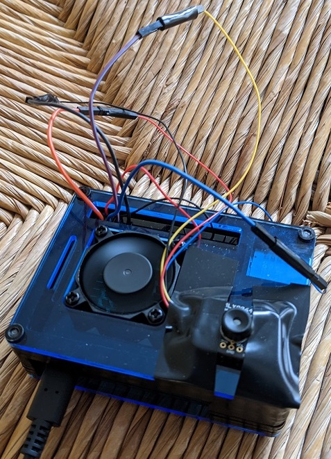
Tom’s setup inside a case with a cooling fan; the camera is taped on bottom right
An affordable solution
His first thought was to get a thermal IR (infrared) camera, but he found the price hasn’t yet come down as much as he’d hoped. They range from several thousand dollars down to a few hundred, with a $50 option just to rent one from a hardware store for 24 hours.
When he saw the $50 option, he realised he could just buy the $60 (£54) MLX90640 Thermal Camera from Pimoroni and attach it to a Raspberry Pi. Tom used a Raspberry Pi 4 for this project. Problem affordably solved.
A joint open source effort
Once Tom’s hardware arrived, he took advantage of the opportunity to combine elements of several other projects that had caught his eye into a single, consolidated Python library that can be downloaded via pip and run both locally and as a web server. Tom thanks Валерий Курышев, Joshua Hrisko, and Adrian Rosebrock for their work, on which this solution was partly based.
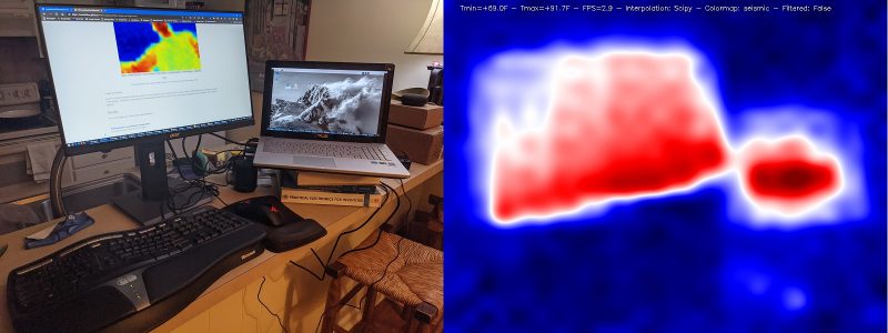
The heat image on the right shows that Tom’s computer and laptop screens are the hottest parts of the room
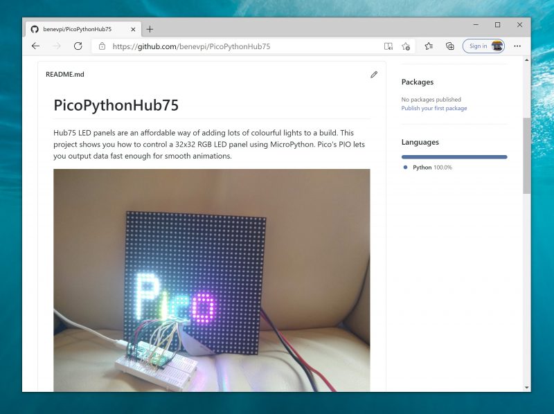
Tom has also published everything on GitHub for further open source development by any enterprising individuals who are interested in taking this even further.
Quality images
The big question, though, was whether the image quality would be good enough to be of real use. A few years back, the best cheap thermal IR camera had only an 8×8 resolution – not great. The magic of the MLX90640 Thermal Camera is that for the same price the resolution jumps to 24×32, giving each frame 768 different temperature readings.
Thermal image showing heat generated by a ceiling lamp but lost through windows
Add a bit of interpolation and image enlargement and the end result gets the job done nicely. Stream the video over your local wireless network, and you can hold the camera in one hand and your phone in the other to use as a screen.
Bonus security feature
Bonus: If you leave the web server running when you’re finished thermal imaging, you’ve got yourself an affordable infrared security camera.
Live camera cycling through interpolation and colour modes and varying view
Documentation on the setup, installation, and results are all available on Tom’s GitHub, along with more pictures of what you can expect.
And you can connect with Tom on LinkedIn if you’d like to learn more about this “technically savvy mathematical modeller”.
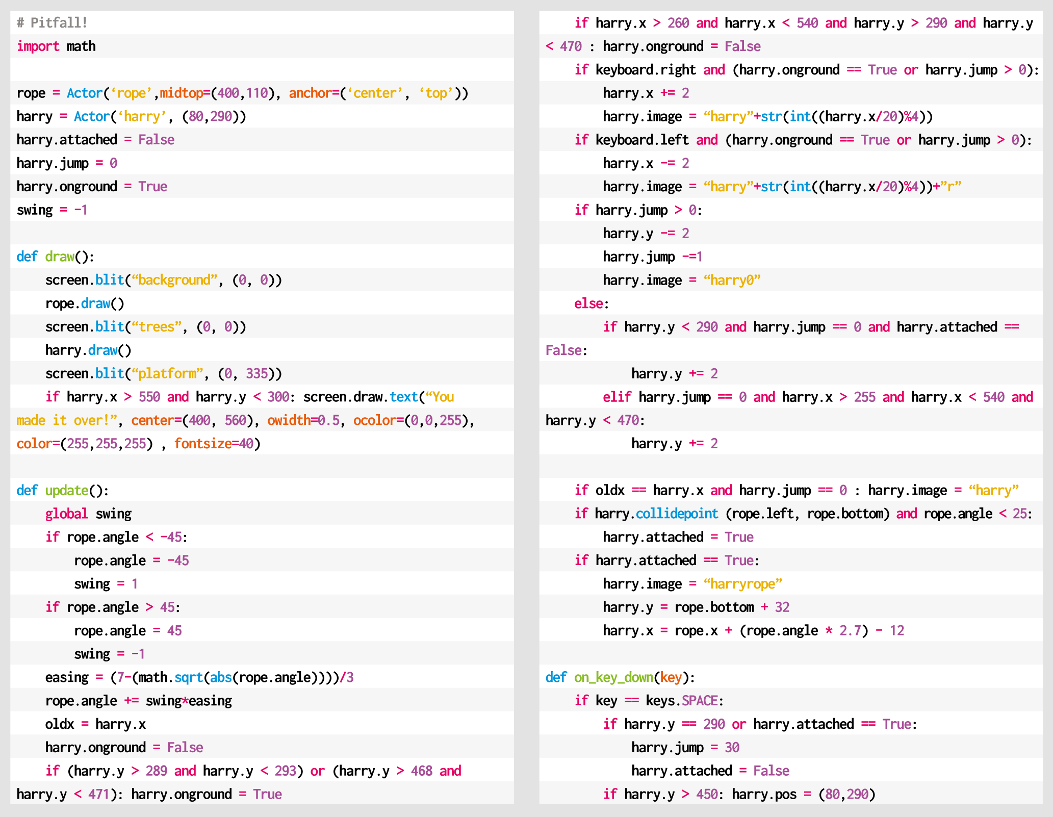
Grab onto ropes and swing across chasms in our Python rendition of an Atari 2600 classic. Mark Vanstone has the code
Whether it was because of the design brilliance of the game itself or because Raiders of the Lost Ark had just hit the box office, Pitfall Harry became a popular character on the Atari 2600 in 1982.
His hazardous attempts to collect treasure struck a chord with eighties gamers, and saw Pitfall!, released by Activision, sell over four million copies. A sequel, Pitfall II: The Lost Caverns quickly followed the next year, and the game was ported to several other systems, even making its way to smartphones and tablets in the 21st century.
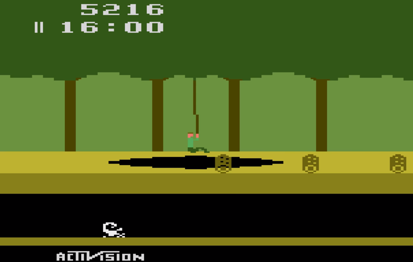
Designed by David Crane, Pitfall! was released for the Atari 2600 and published by Activision in 1982
The game itself is a quest to find 32 items of treasure within a 20-minute time limit. There are a variety of hazards for Pitfall Harry to navigate around and over, including rolling logs, animals, and holes in the ground. Some of these holes can be jumped over, but some are too wide and have a convenient rope swinging from a tree to aid our explorer in getting to the other side of the screen. Harry must jump towards the rope as it moves towards him and then hang on as it swings him over the pit, releasing his grip at the other end to land safely back on firm ground.
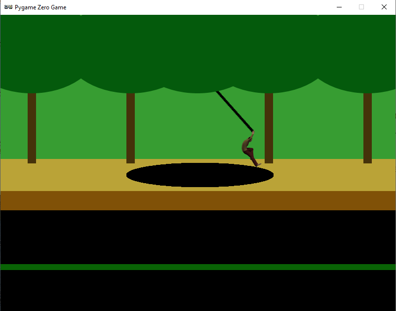
For this code sample, we’ll concentrate on the rope swinging (and catching) mechanic. Using Pygame Zero, we can get our basic display set up quickly. In this case, we can split the background into three layers: the background, including the back of the pathway and the tree trunks, the treetops, and the front of the pathway. With these layers we can have a rope swinging with its pivot point behind the leaves of the trees, and, if Harry gets a jump wrong, it will look like he falls down the hole in the ground. The order in which we draw these to the screen is background, rope, tree-tops, Harry, and finally the front of the pathway.
Now, let’s get our rope swinging. We can create an Actor and anchor it to the centre and top of its bounding box. If we rotate it by changing the angle property of the Actor, then it will rotate at the top of the Actor rather than the mid-point. We can make the rope swing between -45 degrees and 45 degrees by increments of 1, but if we do this, we get a rather robotic sort of movement. To fix this, we add an ‘easing’ value which we can calculate using a square root to make the rope slow down as it reaches the extremes of the swing.
Our homage to the classic Pitfall! Atari game. Can you add some rolling logs and other hazards?
Our Harry character will need to be able to run backwards and forwards, so we’ll need a few frames of animation. There are several ways of coding this, but for now, we can take the x coordinate and work out which frame to display as the x value changes. If we have four frames of running animation, then we would use the %4 operator and value on the x coordinate to give us animation frames of 0, 1, 2, and 3. We use these frames for running to the right, and if he’s running to the left, we just mirror the images. We can check to see if Harry is on the ground or over the pit, and if he needs to be falling downward, we add to his y coordinate. If he’s jumping (by pressing the SPACE bar), we reduce his y coordinate.
We now need to check if Harry has reached the rope, so after a collision, we check to see if he’s connected with it, and if he has, we mark him as attached and then move him with the end of the rope until the player presses the SPACE bar and he can jump off at the other side. If he’s swung far enough, he should land safely and not fall down the pit. If he falls, then the player can have another go by pressing the SPACE bar to reset Harry back to the start.
That should get Pitfall Harry over one particular obstacle, but the original game had several other challenges to tackle – we’ll leave you to add those for yourselves.
Here’s Mark’s code for a Pitfall!-style platformer. To get it working on your system, you’ll need to install Pygame Zero. And to download the full code and assets, head here.
Get your copy of Wireframe issue 48
You can read more features like this one in Wireframe issue 48, available directly from Raspberry Pi Press — we deliver worldwide.
And if you’d like a handy digital version of the magazine, you can also download issue 48 for free in PDF format.
Our Chief Operating Officer and Hardware Lead James Adams talked to The MagPi Magazine about building Raspberry Pi’s first microcontroller platform.
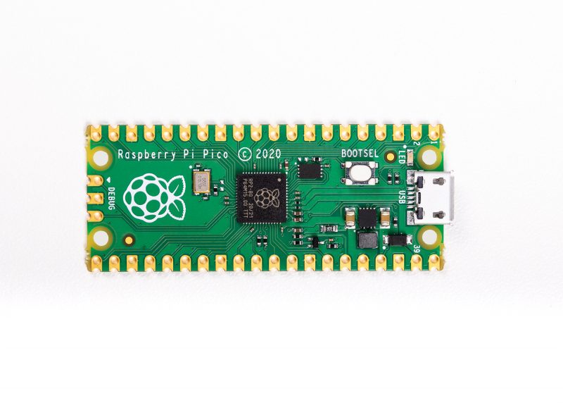
On 21 January we launched the $4 Raspberry Pi Pico. As I write, we’ve taken orders for nearly a million units, and are working hard to ramp production of both the Pico board itself and the chip that powers it, the Raspberry Pi RP2040.
Microcontrollers are a huge yet largely unseen part of our modern lives. They are the hidden computers running most home appliances, gadgets, and toys. Pico and RP2040 were born of our desire to do for microcontrollers what we had done for computing with the larger Raspberry Pi boards. We wanted to create an innovative yet radically low-cost platform that was easy to use, powerful, yet flexible.
It became obvious that to stand out from the crowd of existing products in this space and to hit our cost and performance goals, we would need to build our own chip.
I and many of the Raspberry Pi engineering team have been involved in chip design in past lives, yet it took a long time to build a functional chip team from scratch. As well as requiring specialist skills, you need a lot of expensive tools and IP; and before you can buy these things, there is a lot of work required to evaluate and decide exactly which expensive goodies you’ll need. After a slow start, for the past couple of years we’ve had a small team working on it full-time, with many others pulled in to help as needed.
Low-cost and flexible
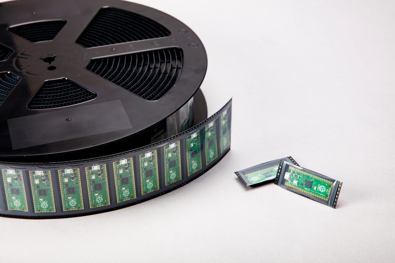
The Pico board was designed alongside RP2040 – in fact we designed the RP2040 pinout to work well on Pico, so we could use an inexpensive two-layer PCB, without compromising on the layout. A lot of thought has gone into making it as low-cost and flexible as possible – from the power circuitry to packaging the units on to Tape and Reel (which is cost-effective and has good packing density, reducing shipping costs).
“This ‘full stack’ design approach has allowed optimisation across the different parts”
With Pico we’ve hit the ‘pocket money’ price point, yet in RP2040 we’ve managed to pack in enough CPU performance and RAM to run more heavyweight applications such as MicroPython, and AI workloads like TinyML. We’ve also added genuinely new and innovative features such as the Programmable I/O (PIO), which can be programmed to ‘bit-bang’ almost any digital interface without using valuable CPU cycles. Finally, we have released a polished C/C++ SDK, comprehensive documentation and some very cool demos!
For me, this project has been particularly special as I began my career at a small chip-design startup. This was a chance to start from a clean sheet and design silicon the way we wanted to, and to talk about how and why we’ve done it, and how it works.
Pico is also our most vertically integrated product; meaning we control everything from the chip through to finished boards. This ‘full stack’ design approach has allowed optimisation across the different parts, creating a more cost-effective and coherent whole (it’s no wonder we’re not the only fruit company doing this).
And of course, it is designed here in Cambridge, birthplace of so many chip companies and computing pioneers. We’re very pleased to be continuing the Silicon Fen tradition.
Get The MagPi 103 now
You can grab the brand-new issue right now online from the Raspberry Pi Press store, or via our app on Android or iOS. You can also pick it up from supermarkets and newsagents, but make sure you do so safely while following all your local guidelines.
Finally, there’s also a free PDF you can download. Good luck during the #MonthOfMaking, folks! I’ll see y’all online.
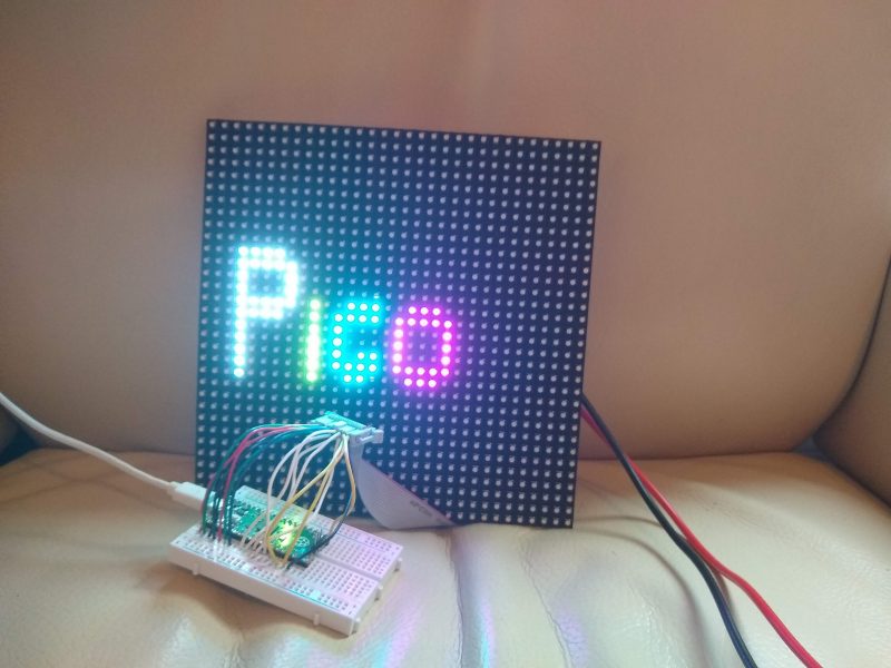
HUB75 LED panels provide an affordable way to add graphical output to your projects. They were originally designed for large advertising displays (such as the ones made famous by Piccadilly Circus in London, and Times Square in New York). However, we can use a little chunk of these bright lights in our projects. They’re often given a ‘P’ value, such as P3 or P5 for the number of millimetres between the different RGB LEDs. These don’t affect the working or wiring in any way.
We used a 32×32 Adafruit screen. Other screens of this size may work, or may be wired differently. It should be possible to get screens of different sizes working, but you’ll have to dig through the code a little more to get it running properly.
The most cost- effective way to add 1024 RGB LEDs to your project
The protocol for running these displays involves throwing large amounts of data down six different data lines. This lets you light up one portion of the display. You then switch to a different portion of the display and throw the data down the data lines again. When you’re not actively writing to a particular segment of the display, those LEDs are off.
There’s no in-built control over the brightness levels – each LED is either on or off. You can add some control over brightness by flicking pixels on and off for different amounts of time, but you have to manage this yourself. We won’t get into that in this tutorial, but if you’d like to investigate this, take a look at the box on ‘Going Further’.
The first thing you need to do is wire up the screen. There are 16 connectors, and there are three different types of data sent – colour values, address values, and control values. You can wire this up in different ways, but we just used header wires to connect between a cable and a breadboard. See here for details of the connections.
These screens can draw a lot of power, so it’s best not to power them from your Pico’s 5V output. Instead, use a separate 5V supply which can output enough current. A 1A supply should be more than enough for this example. If you’re changing it, start with a small number of pixels lit up and use a multimeter to read the current.
With it wired up, the first thing to do is grab the code and run it. If everything’s working correctly, you should see the word Pico bounce up and down on the screen. It is a little sensitive to the wiring, so if you see some flickering, make sure that the wires are properly seated. You may want to just display the word ‘Pico’. If so, congratulations, you’re finished!
However, let’s take a look at how to customise the display. The first things you’ll need to adapt if you want to display different data are the text functions – there’s one of these for each letter in Pico. For example, the following draws a lower-case ‘i’:
As you can see, this uses the light_xy method to set a particular pixel a particular colour (r, g, and b can all be 0 or 1). You’ll also need your own draw method. The current one is as follows:
This sets the writing global variable to stop it drawing this frame if it’s still being updated, and then just scrolls the text_y variable between 5 and 20 to bounce the text up and down in the middle of the screen.
This method runs on the second core of Pico, so it can still throw out data constantly from the main processing core without it slowing down to draw images.
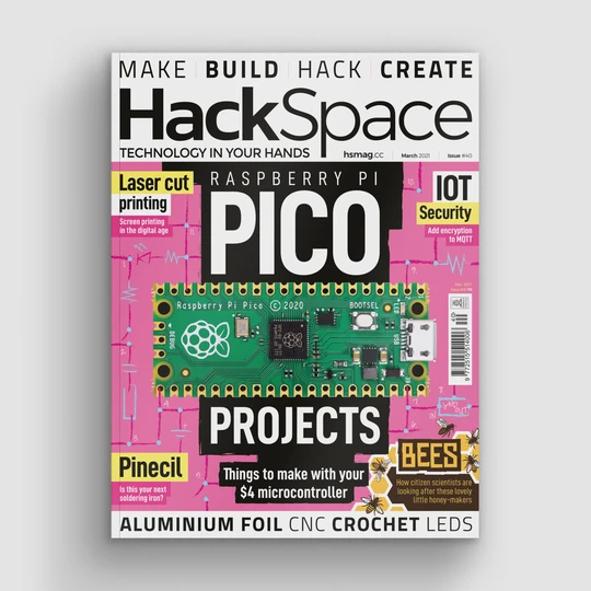
Get HackSpace magazine – Issue 40
Each month, HackSpace magazine brings you the best projects, tips, tricks and tutorials from the makersphere. You can get it from the Raspberry Pi Press online store, The Raspberry Pi store in Cambridge, or your local newsagents.
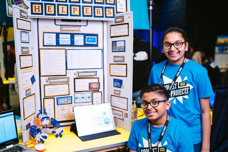
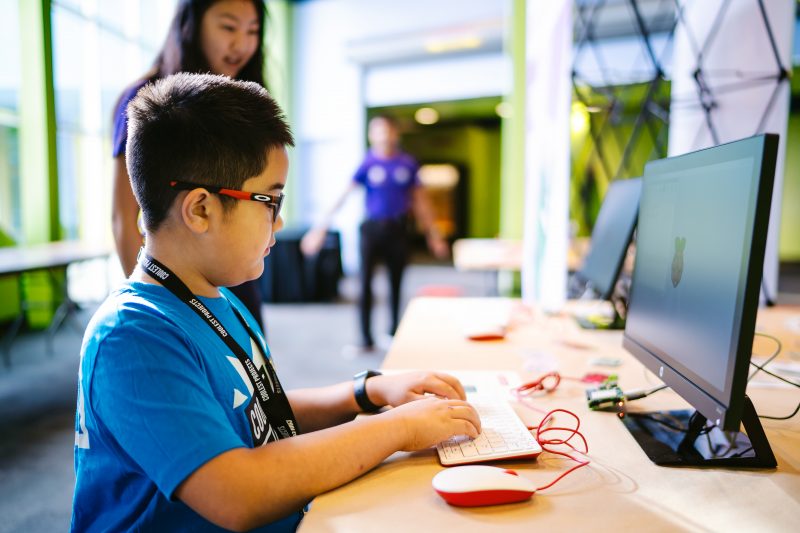
In our free Coolest Projects online showcase, we invite a worldwide community of young people to come together and celebrate what they’ve built with technology. For this year’s showcase, we’ve already got young tech creators from more than 35 countries registered, including from India, Ireland, UK, USA, Australia, Serbia, Japan, and Syria!
Register to become part of the global Coolest Projects community
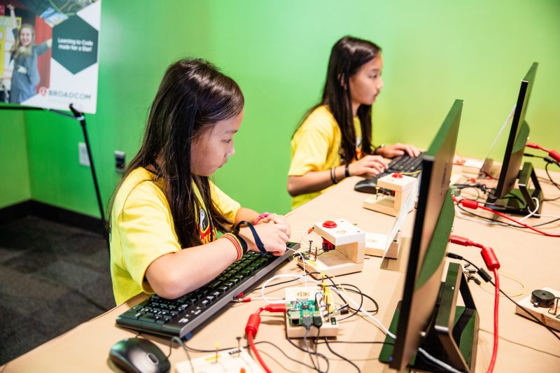
Everyone up to age 18 can register for Coolest Projects to become part of this community with their own tech creation. We welcome all projects, all experience levels, and all kinds of projects, from the very first Scratch animation to a robot with machine learning capacity! The beauty of Coolest Projects is in the diversity of what the young tech creators make.
Young people can register projects in six categories: Hardware, Scratch, Mobile Apps, Websites, Games, and Advanced Programming. Projects need to be fully registered by Monday 3 May 2021, but they don’t need to be finished then — at Coolest Projects we celebrate works in progress just as much as finished creations!
To learn more about the registration process, watch the video below or read our guide on how to register.
Our Coolest Projects support for young people and you
Here are the different ways we’re supporting your young people — and you — with project creation!
Online resources for designing and creating projects
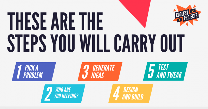
Download the free Coolest Projects workbook that walks young people through the whole creation process, from finding a topic or problem they want to address, to idea brainstorming, to testing their project:
Our Coolest Projects worksheets have detailed guidance about all five steps of project creation.
This Wednesday 3 March at 19:00 GMT / 14:00 ET, young people can join a special Digital Making at Homelive stream about capturing ideas for projects. We’ll share practical tips and inspiration to help them get started with building a Coolest Projects creation:
On Tuesday 23 March, 16:00 GMT / 11:00 ET, young people can join the Coolest Projects team on a live stream to talk to them about all things Coolest Projects and ask all their questions! Subscribe to our YouTube channel and turn on notifications to be reminded about this live stream.
Online workshops for educators & parents
Join our free online workshops where you as an educator or parent can learn how to best support young people to take part:
How to support project making remotely — a live online workshop on 11 March at 11:00 GMT / 16:30 IST / 19:00 AWST. Register so you can attend live or receive the video recording later.
Celebrating young people’s creativity
Getting creative with technology is truly empowering for young people, and anything your young people want to create will be celebrated by us and the whole Coolest Projects community. We’re so excited to see their projects, and we can’t wait to celebrate all together at our big live stream celebration event in June! Don’t let your young people miss their chance to be part of the fun.
Pi Day is a special occasion for people all around the world (your preferred date format notwithstanding), and I love seeing all the ways that makers, students, and educators celebrate. This year at the Raspberry Pi Foundation, we’re embracing Pi Day as a time to support young learners and creators in our community. Today, we launch our first Pi Day fundraising campaign. From now until 14 March, I’d like to ask for your help to empower young people worldwide to learn computing and become confident, creative digital makers and engineers.
Millions of learners use the Raspberry Pi Foundation’s online coding projects to develop new skills and get creative with technology. Your donation to the Pi Day campaign will support young people to access these high-quality online resources, which they need more urgently than ever amidst disruptions to schools and coding clubs. Did I mention that our online projects are offered completely free and in dozens of languages? That’s possible thanks to Raspberry Pi customers and donors who power our educational mission.
It’s not only young people who rely on the Raspberry Pi Foundation’s free online coding projects, but also teachers, educators, and volunteers in coding clubs:
“The project resources for Python and Scratch make it really easy for the children to learn programming and create projects successfully, even if they have limited prior experience — they are excellent.”
— Code Club educator in the UK
“The best thing […] is the accessibility to a variety of projects and ease of use for a variety of ages and needs. I love checking the site for what I may have missed and the next project my students can do!”
Your Pi Day gift will make double the impact thanks to our partner EPAM, who is generously matching all donations up to a total of $5000. As a special thanks to each of you who contributes, you’ll have the option to see your name listed in an upcoming issue of The MagPi magazine!
All young people deserve the opportunity to thrive in today’s technology-driven world. As a donor to the Raspberry Pi Foundation, you can make this a reality. Any amount you are able to give to our Pi Day campaign — whether it’s $3.14, $31.42, or even more — makes a difference. You also have the option to sign up as a monthly donor.
Let’s come together to give young people the tools they need to make things, solve problems, and shape their future using technology. Thank you.
PS Thanks again to EPAM for partnering with us to match your gifts up to $5000 until 14 March, and to CanaKit for their generous Pi Day contribution of $3141!
Hey folks, Rob from The MagPi here! I hope you’ve been doing well. Despite how it feels, a brand-new March is just around the corner. Here at The MagPi, we like to celebrate March with our annual #MonthOfMaking event, where we want to motivate you to get making.
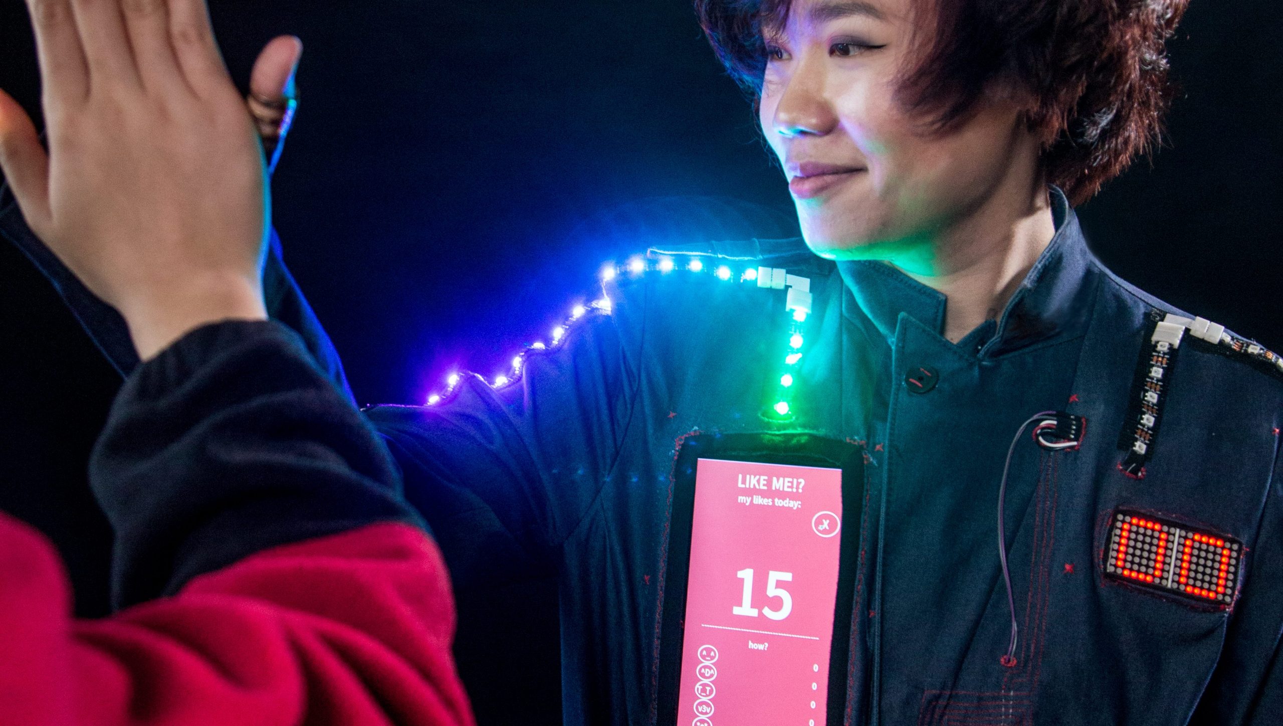
You could make tech you can wear
But what should I make?
Making what? Anything you want. Flex your creative building skills with some programming, or circuity, or woodworking, metalwork, knitting, baking, photography, and whatever else you’ve been wanting to try out. Just make it, and share it with the hashtag #MonthOfMaking.
You could make something to hide in nature while you capture… nature
In The MagPi 103 we have a big feature on alternative ways you can make — at least alternative to what we usually cover in the magazine. From sewing and embroidery to recycling and animation, we hope you’ll be inspired to try something new.
Try something new with Raspberry Pi Pico
I’ve got a few projects lined up myself, including some Raspberry Pi Pico stuff I’ve been mulling over.
You could make a chandelier light fitting out of drinks bottles?!
Speaking of: we also show you some easy Raspberry Pi Pico projects to celebrate its recent release! You’ll discover all the ways you can get started with and learn more about Raspberry Pi’s first microcontroller.
All this and our usual selection of articles on weather maps, on-air lights, meme generators, hardware reviews, and much more is packed into issue 103!
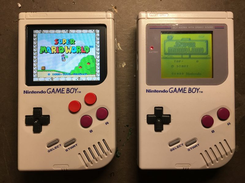
Maybe you could tinker with some old tech
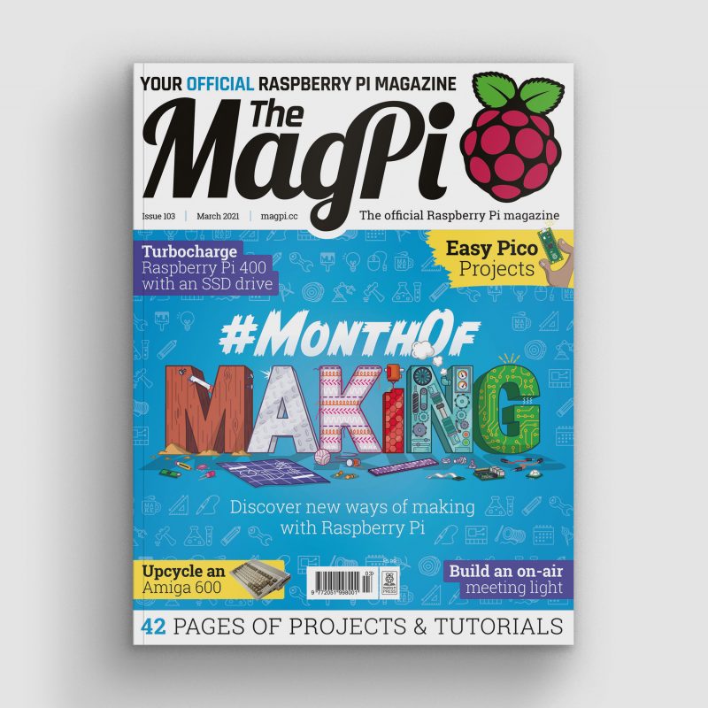
Get The MagPi 103 now
You can grab the brand-new issue right now online from the Raspberry Pi Press store, or via our app on Android or iOS. You can also pick it up from supermarkets and newsagents, but make sure you do so safely while following all your local guidelines.
Finally, there’s also a free PDF you can download. Good luck during the #MonthOfMaking, folks! I’ll see y’all online.
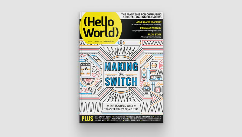
In our brand-new issue of Hello World magazine, Hayley Leonard from our team gives a primer on how computing educators can apply the Universal Design for Learning framework in their lessons.
Universal Design for Learning (UDL) is a framework for considering how tools and resources can be used to reduce barriers and support all learners. Based on findings from neuroscience, it has been developed over the last 30 years by the Center for Applied Special Technology (CAST), a nonprofit education research and development organisation based in the US. UDL is currently used across the globe, with research showing it can be an efficient approach for designing flexible learning environments and accessible content.
Engaging a wider range of learners is an important issue in computer science, which is often not chosen as an optional subject by girls and those from some minority ethnic groups. Researchers at the Creative Technology Research Lab in the US have been investigating how UDL principles can be applied to computer science, to improve learning and engagement for all students. They have adapted the UDL guidelines to a computer science education context and begun to explore how teachers use the framework in their own practice. The hope is that understanding and adapting how the subject is taught could help to increase the representation of all groups in computing.
The UDL guidelines help educators anticipate barriers to learning and plan activities to overcome them.
A scientific approach
The UDL framework is based on neuroscientific evidence which highlights how different areas or networks in the brain work together to process information during learning. Importantly, there is variation across individuals in how each of these networks functions and how they interact with each other. This means that a traditional approach to teaching, in which a main task is differentiated for certain students with special educational needs, may miss out on the variation in learning between all students across different tasks.
The UDL framework is based on neuroscientific evidence
The UDL guidelines highlight different opportunities to take learner differences into account when planning lessons. The framework is structured according to three main principles, which are directly related to three networks in the brain that play a central role in learning. It encourages educators to plan multiple, flexible methods of engagement in learning (affective networks), representation of the teaching materials (recognition networks), and opportunities for action and expression of what has been learnt (strategic networks).
The three principles of UDL are each expanded into guidelines and checkpoints that allow educators to identify the different methods of engagement, representation, and expression to be used in a particular lesson. Each principle is also broken down into activities that allow learners to access the learning goals, remain engaged and build on their learning, and begin to internalise the approaches to learning so that they are empowered for the future.
Examples of UDL guidelines for computer science education from the Creative Technology Research Lab
Multiple means of engagement
Multiple means of representation
Multiple means of action and expression
Provide options for recruiting interests * Give students choice (software, project, topic) * Allow students to make projects relevant to culture and age
Provide options for perception * Model computing through physical representations as well as through interactive whiteboard/videos etc. * Select coding apps and websites that allow adjustment of visual settings (e.g. font size/contrast) and that are compatible with screen readers
Provide options for physical action * Include CS unplugged activities that show physical relationships of abstract computing concepts * Use assistive technology, including a larger or smaller mouse or touchscreen devices
Provide options for sustaining effort and persistence * Utilise pair programming and group work with clearly defined roles * Discuss the integral role of perseverance and problem-solving in computer science
Provide options for language, mathematical expressions, and symbols * Teach and review computing vocabulary (e.g. code, animations, algorithms) * Provide reference sheets with images of blocks, or with common syntax when using text
Provide options for expression and communication * Provide sentence starters or checklists for communicating in order to collaborate, give feedback, and explain work * Provide options that include starter code
Provide options for self-regulation * Break up coding activities with opportunities for reflection, such as ‘turn and talk’ or written questions * Model different strategies for dealing with frustration appropriately
Provide options for comprehension * Encourage students to ask questions as comprehension checkpoints * Use relevant analogies and make cross-curricular connections explicit
Provide options for executive function * Embed prompts to stop and plan, test, or debug throughout a lesson or project * Demonstrate debugging with think-alouds
Each principle of the UDL framework is associated with three areas of activity which may be considered when planning lessons or units of work. It will not be the case that each area of activity should be covered in every lesson, and some may prove more important in particular contexts than others. The full table and explanation can be found on the Creative Technology Research Lab website at ctrl.education.ufl.edu/projects/tactic.
Applying UDL to computer science education
While an advantage of UDL is that the principles can be applied across different subjects, it is important to think carefully about what activities to address these principles could look like in the case of computer science.
Researcher Maya Israel will speak at our April seminar
Researchers at the Creative Technology Research Lab, led by Maya Israel, have identified key activities, some of which are presented in the table on the previous page. These guidelines will help educators anticipate potential barriers to learning and plan activities that can overcome them, or adapt activities from those in existing schemes of work, to help engage the widest possible range of students in the lesson.
UDL in the classroom
As well as suggesting approaches to applying UDL to computer science education, the research team at the Creative Technology Research Lab has also investigated how teachers are using UDL in practice. Israel and colleagues worked with four novice computer science teachers in US elementary schools to train them in the use of UDL and understand how they applied the framework in their teaching.
The research found that the teachers were most likely to include in their teaching multiple means of engagement, followed by multiple methods of representation. For example, they all offered choice in their students’ activities and provided materials in different formats (such as oral and visual presentations and demonstrations). They were less likely to provide multiple means of action and expression, and mainly addressed this principle through supporting students in planning work and checking their progress against their goals.
Although the study included only four teachers, it highlighted the flexibility of the UDL approach in catering for different needs within variable teaching contexts. More research will be needed in future, with larger samples, to understand how successful the approach is in helping a wide range of students to achieve good learning outcomes.
Find out more about using UDL
There are numerous resources designed to help teachers learn more about the UDL framework and how to apply it to teaching computing. The CAST website (helloworld.cc/cast) includes an explainer video and the detailed UDL guidelines. The Creative Technology Research Lab website has computing-specific ideas and lesson plans using UDL (helloworld.cc/udl).
Maya Israel will be presenting her research at our computing education research seminar series, on 20 April 2021. Our seminars are free to attend and open to anyone from anywhere around the world. Find out more about the current seminar series, which focuses on diversity and inclusion, and sign up to attend for free.
Israel, M., Jeong, G., Ray, M., & Lash, T. (2020). Teaching Elementary Computer Science Through Universal Design for Learning. Proceedings of the 51st ACM Technical Symposium on Computer Science Education, pp. 1220-1226. dl.acm.org/doi/abs/10.1145/3328778.3366823
Rose, D. H. & Strangman, N. (2007). Universal design for learning: Meeting the challenge of individual learning differences through a neurocognitive perspective. Universal Access in the Information Society, 5(4), pp. 381-391. dl.acm.org/doi/abs/10.1007/s10209-006-0062-8
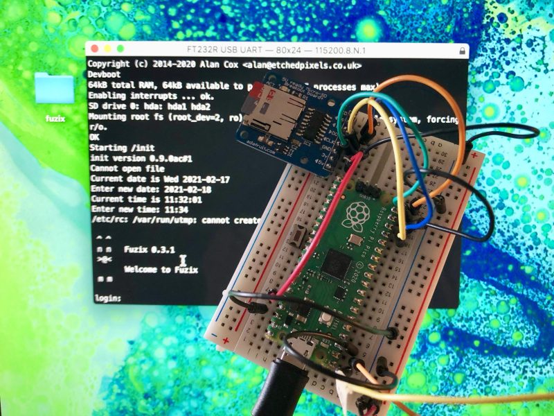
FUZIX is an old-school Unix clone that was initially written for the 8-bit Zilog Z80 processor and released by Alan Cox in 2014. At one time one of the most active Linux developers, Cox stepped back from kernel development in 2013. While the initial announcement has been lost in the mists because he made it on the now defunct Google+, Cox jokingly recommended the system for those longing for the good old days when all the source code still fitted on a single floppy disk.
FUZIX running on Raspberry Pi Pico.
Since then FUZIX has been ported to other architectures such as 6502, 68000, and the MSP430. Earlier in the week David Given — who wrote both the MSP430 and ESP8266 ports — went ahead and ported it to Raspberry Pi Pico and RP2040.
FUZIX is a “proper” Unix with a serial console on Pico’s UART0 and SD card support, using the card both for the filesystem and for swap space. While there is a binary image available, it’s easy enough to build from source.
If you don’t already have the Raspberry Pi Pico toolchain set up and working you should go ahead and set up the C/C++ SDK.
Afterwards you need grab the the Pico port from GitHub.
and edit the first line of the Makefile to set the path to your pico-sdk.
So for instance if you’re building things on a Raspberry Pi and you’ve run the pico_setup.sh script, or followed the instructions in our Getting Started guide, you’d point the PICO_SDK_PATH to
If everything goes well you should have a UF2 file in build/fuzix.uf2 and a filesystem.img image file in your current working directory.
You can now load the UF2 file onto your Pico in the normal way.
Go grab your Raspberry Pi Pico board and a micro USB cable. Plug the cable into your Raspberry Pi or laptop, then press and hold the BOOTSEL button on your Pico while you plug the other end of the micro USB cable into the board. Then release the button after the board is plugged in.
A disk volume called RPI-RP2 should pop up on your desktop. Double-click to open it, and then drag and drop the UF2 file into it.
The volume will automatically unmount, and your Pico is now running Unix. Unfortunately it won’t be much use without a filesystem.
Building a bootable SD card
The filesystem.img image file we built earlier isn’t a bootable image. Unlike the Raspberry Pi OS images you might be used to, you can’t just use something like Raspberry Pi Imager to write it to an SD card. We’re going to have to get our hands a bit dirtier than that.
The following instructions are for building your file system on a Raspberry Pi, or another similar Linux platform. Comparable tools are available on both MS Windows and Apple macOS, but the exact details will differ.
Go grab a microSD card. As the partitions we’re going to put onto it are only going to take up 34MB it doesn’t really matter what size you’ve got to hand. I was using a 4GB card, as that was the smallest I could find, but it’s not that important.
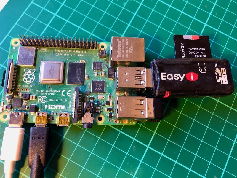
Now plug the card into a USB card reader and then into your Raspberry Pi or laptop computer. We’re going to have to build the partition table that FUZIX is expecting, which consists of two partitions: the first a 2MB swap partition, and the second a 32MB root partition into which we can copy the root filesystem, our filesystem.img file.
Raspberry Pi 4 with USB card reader.
After plugging your card into the reader you can find it from the command line using the lsblk command. If you’ve have a blank unformatted card it will be visible as /dev/sda.
Depending on the initial state of your disk you may be prompted that the partition “contains a vfat signature” and asked whether you want to remove the signature. If asked, just type “Y” to confirm.
Next, we’ll set the type for this partition to “7F“
You can now eject the SD card from the USB card reader, because it’s time to wire up our breadboard.
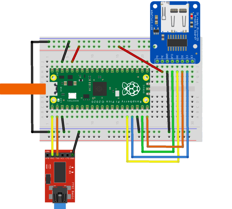
Wiring things up on the breadboard
If you’re developing on a Raspberry Pi, and you haven’t previously used UART serial — which is different from the “normal” USB serial — you should go read Section 4.5 of our Getting Started guide.
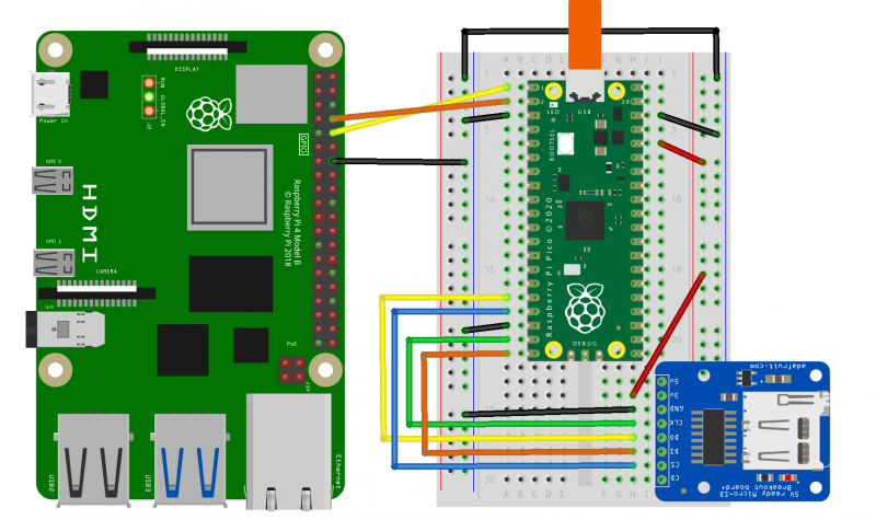
Connecting a Raspberry Pi to a Pico and SD card.
Here I’m using Adafruit’s MicroSD Card Breakout, and wiring the UART serial connection directly to to the Raspberry Pi’s serial port using the GPIO headers.
However, if you’re developing on a laptop you can use something like the SparkFun FTDI Basic Breakout to connect the serial UART to your computer. Again, see our Getting Started guide for details: Section 9.1.4 if you’re on Apple macOS, or Section 9.2.5 if you’re on MS Windows.
Connecting a laptop to a Pico and SD card.
Either way, the mapping between the pins on your Raspberry Pi Pico and the SD card breakout is the same, and should be as follows:
Pico
RP2040
SD Card
3V3 (OUT)
—
+3.3V
Pin 16
GP12 (SPI1 RX)
DO (MISO)
Pin 17
GP13 (SPI1 CSn)
CS
Pin 18
GND
GND
Pin 19
GP14 (SPI1 SCK)
SCK
Pin 20
GP15 (SPI1 TX)
DI (MOSI)
Mapping between physical pin number, RP2040 pin, and SD Card breakout.
Once you’ve wired things up, pop your formatted microSD card into the breadboarded SD card breakout, and plug your Raspberry Pi Pico into USB power. FUZIX will boot automatically.
Connecting to FUZIX
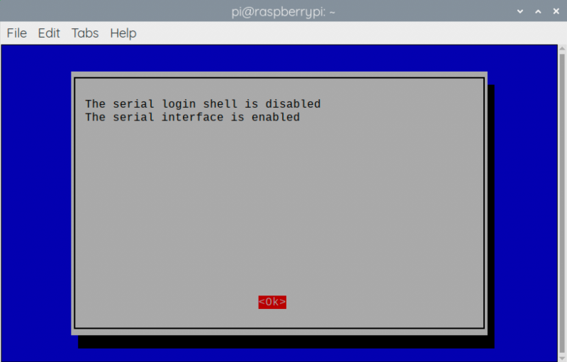
If you’re connecting using a Raspberry Pi, the first thing you’ll need to do is enable UART serial communications using raspi-config.
Go to Interfacing Options → Serial. Select “No” when asked “Would you like a login shell to be accessible over serial?” and “Yes” when asked “Would you like the serial port hardware to be enabled?”
Enabling a serial UART using raspi-config on Raspberry Pi.
Leaving raspi-config you should choose “Yes” and reboot your Raspberry Pi to enable the serial port. More information about connecting via UART can be found in Section 4.5 of our Getting Started guide.
Alternatively, if you are working on a laptop from macOS or MS Windows you can use minicom, screen, or your usual Terminal program. If you’re unsure what to use, there are a number of options: for instance, a good option is CoolTerm, which is cross-platform and works on Linux, macOS, and Windows.
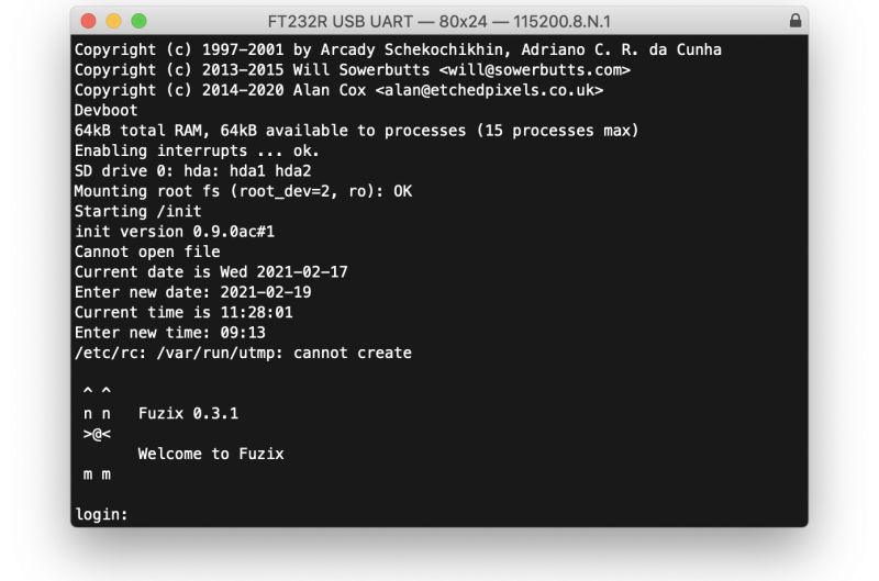
After connecting to the serial port you should see something like this:
If you don’t see anything, just unplug and replug your Pico to reset it and start FUZIX running again.
Finally, go ahead and enter the correct date and time, and when you get to the login prompt you can login as “root” with no password.
Welcome to FUZIX!
Wrapping up
While there are still a few problems, the port of FUZIX to Pico has been merged to the upstream repository, which means it’s now an official part of the operating system.
Support for developing for Pico can be found on the Raspberry Pi forums. There is also an (unofficial) Discord server where a lot of people active in the new community seem to be hanging out. Feedback on the documentation should be posted as an Issue to the pico-feedback repository on GitHub, or directly to the relevant repository it concerns.
All of the documentation, along with lots of other help and links, can be found on the Getting Started page. If you lose track of where that is in the future, you can always find it from your Pico: to access the page, just press and hold the BOOTSEL button on your Pico, plug it into your laptop or Raspberry Pi, then release the button. Go ahead and open the RPI-RP2 volume, and then click on the INDEX.HTM file.
One of the harsh lessons we learned last year was that far too many young people still don’t have a computer for learning at home. There has always been a digital divide; the pandemic has just put it centre-stage. The good news is that the cost of solving this problem is now trivial compared to the cost of allowing it to persist.
Removing price as a barrier to anyone owning a computer was part of the founding mission of Raspberry Pi, which is why we so work hard to make sure that Raspberry Pi computers are as low-cost as possible for everyone, all of the time. We saw an incredible rise in the numbers of people — particularly young people — using Raspberry Pi computers as their main desktop PC during the lockdown, helped by the timely arrival of the fabulous Raspberry Pi 400.
Supporting the most vulnerable young people
As part of our response to the pandemic, the Raspberry Pi Foundation teamed up with UK Youth and a network of grassroots youth and community organisations to get Raspberry Pi desktop kits (with monitors, webcams, and headphones) into the hands of disadvantaged young people across the UK. These were young people who didn’t qualify for the government laptop scheme and who otherwise didn’t have a computer to learn at home.
This wasn’t just about shipping hardware (that’s the easy bit). We trained youth workers and teachers, and we worked closely with families to make sure that they could set up and use the computers. We did a huge amount of work to make sure that the educational platforms and apps they needed worked out of the box, and we provided a customised operating system image with free educational resources and enhanced parental controls.
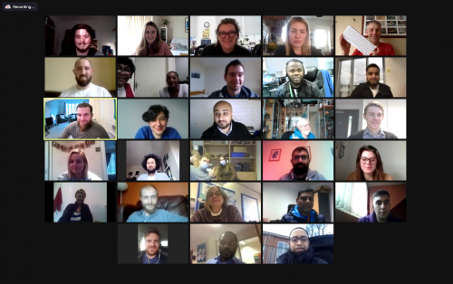
One of our training calls for the adults who will be supporting young people and families to use the Raspberry Pi kits
The impact has been immediate: young people engaging with learning; parents who reported positive changes in their children’s attitude and behaviour; youth and social workers who have deepened their relationship with families, enabling them to provide better support.
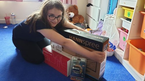
After a successful pilot programme generously funded by the Bloomfield Trust, we launched the Learn at Home fundraising campaign in December, inviting businesses and individuals to donate money to enable us to expand the programme. I am absolutely thrilled that more than 70 organisations and individuals have so far donated an incredible £900,000 and we are on track to deliver our 5000th Raspberry Pi kit in March.
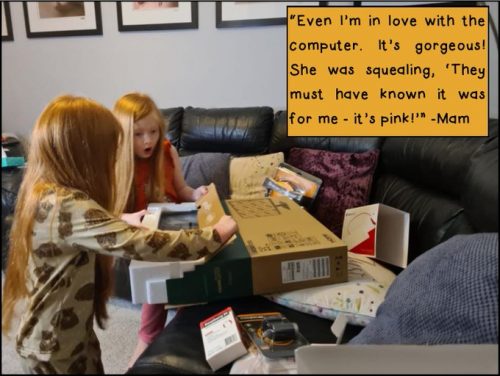
Thanks to Gillas Lane Primary Academy for collecting some wonderful photos and quotes illustrating the impact our computers are having!
While the pandemic shone a bright spotlight onto the digital divide, this isn’t just a problem while we are in lockdown. We’ve known for a long time that having a computer to learn at home can be transformational for any young person.
If you would like to get involved in helping us make sure that every young person has access to a computer to learn at home, we’d love to hear from you. Find out more details on our website, or email us at partners@raspberrypi.org.
We shared Dennis Mellican’s overly effective anti-burglary project last month. Now he’s back with something a whole lot more musical and mini.
Inspiration
Dennis was inspired by other jukebox projects that use Raspberry Pi, NFC readers, and tags to make music play. Particularly this one by Mark Hank, which we shared on the blog last year. The video below shows Dennis’s first attempt at creating an NFC Raspberry Pi music player, similar to Mark’s.
LEGO twist
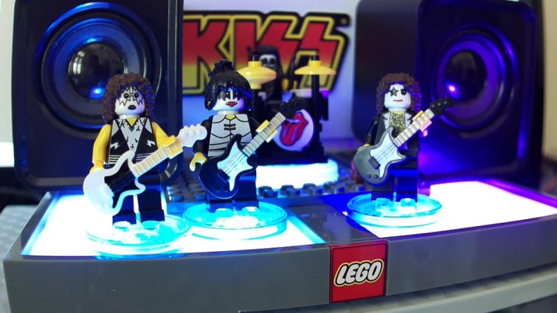
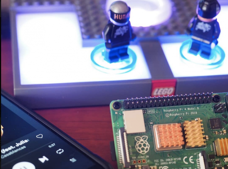
After some poking around, Dennis realised that the LEGO Dimensions toy pad is a three-in-one NFC reader with its own light show. He hooked it up to a Raspberry Pi and developed a Python application to play music when LEGO Dimension Minifigures are placed on the toy pad. So, if an Elvis minifigure is placed on the reader, you’ll hear Elvis’s music.
Mini KISS rocking out on the NFC reader
The Raspberry Pi is hooked up to the LEGO Dimensions toy pad, with Musicfig (Dennis’s name for his creation) playing tracks via Spotify over Bluetooth. The small screen behind the minifigures is displaying the Musicfig web application which, like the Spotify app, displays the album art for the track that’s currently playing.
No Spotify or LEGO? No problem!
Daft Punk LOVES Raspberry Pi
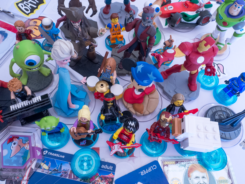
Spotify playback is optional, as you can use your own MP3 music file collection instead. You also don’t have to use LEGO Minifigures: most NFC-enabled devices or tags can be used, including Disney Infinity, Nintendo Amiibo, and Skylander toy characters.
Why not have Elsa sing… what’s that song again? Let it… what was it?
Dennis thought Musicfig could be a great marketable LEGO product for kids and grown-ups alike, and and he submitted it to the LEGO Ideas website. Unfortunately, he had tinkered a little too much (we approve) and it wasn’t accepted, due to rules that don’t allow non-LEGO parts or customisations.
Want to build one?
The LEGO Dimensions toy pad was discontinued in 2017, but Dennis has seen some sets on sale at a few department stores, and even more cheaply on second-hand market sites like Bricklink. We’ve spotted them on eBay and Amazon too. Dennis also advises that the toy pad often sells for less than a dedicated NFC reader.
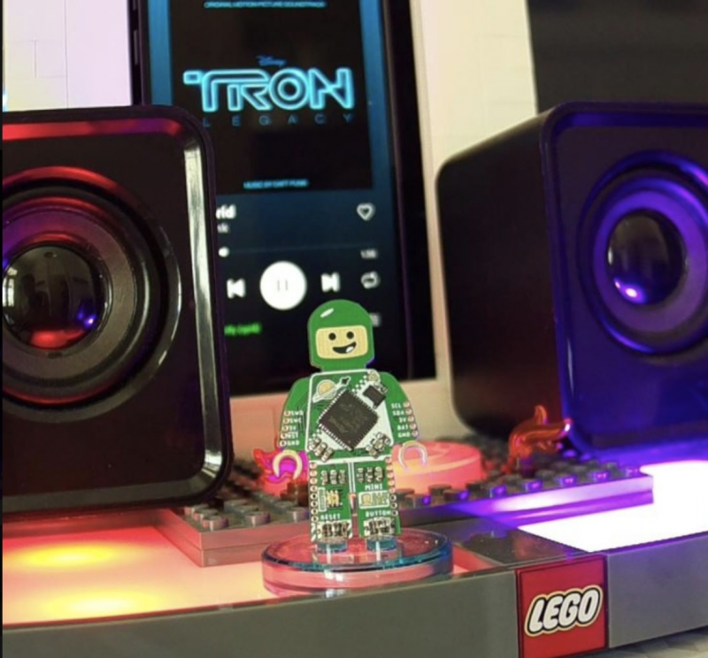
What’s the best movie soundtrack and why is it Tron?
Watch Dennis’s seven-year-old son Benny show you how it all works, from Elvis through to Prodigy via Daft Punk and Queen.
You can tell which songs Benny likes best because the volume goes to 11
There are some really simple step-by-step instructions for a quick install here, as well as a larger gallery of Musicfig rigs. And Dennis hosts a more detailed walkthrough of the project, plus code examples, here.
You can find all things Dennis-related, including previous Raspberry Pi projects, here.
This twinkly tutorial is fresh from the latest issue of HackSpace magazine, out now.
Adding flashing lights to a project is a great way to make it a little more visually appealing, and WS2812B LEDs (sometimes known as NeoPixels) are a great way to do that.
They have their own mini communications protocol, so you can control lots of them with just a single pin on your microcontroller, and there’s a handy library for Pico MicroPython that lets you control them.
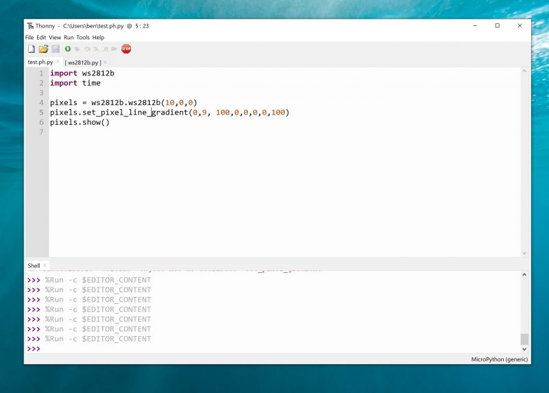
First, you need to grab the library from hsmag.cc/PicoPython and copy the PY file to your Pico device. You can do this by opening the file in Thonny and clicking Save As, and then selecting your MicroPython device and calling it ws2812b.py.
You create an object with the following parameters: number of LEDs, state machine ID, and GPIO number, in that order. So, to create a strip of ten LEDs on state machine 0 and GPIO 0, you use:
pixels = ws2812b.ws2812b(10,0,0)
This object has two methods: show() which sends the data to the strip, and set_pixel which sets the colour values for a particular LED. The parameters are LED number, red, green, blue, with the colours taking values between 0 and 255.
At the time of writing, there’s an issue using this library in the interpreter. The author is investigating, but it’s best to run it from saved files to ensure everything runs properly. Create a file with the following and run it:
So, now we can light up some LEDs, let’s take a look at how to turn this into an interesting light fixture.
We originally created the fireflies example in the WS2812B project for Christmas tree lights, but once the festive season was over, we liked them so much that we wanted to keep them going year round. Obviously, we can’t just keep a tree up all the time, so we needed another way to display them. We’re using them on thin-wire WS2812B LEDs that are available from direct-from-China sellers, but they should work on other types of WS2812B-compatible LEDs.
There are some other methods in the WS2812B module, such as set_pixel_line_gradient() to add effects to your projects
For display, we’ve put the string of LEDs into a glass demijohn that we used to use for brewing, but any large glass jar would work. This gives an effect inspired by fireflies trapped in a jar. You can just download the code and run it (it’s in the examples folder in the above repository), but let’s take a look and see how it works. The first part of the code sets everything up:
import time
import ws2812b
import random
bright_div = 20
numpix = 50 # Number of NeoPixels
strip = ws2812b.ws2812b(numpix, 0,0)
You can change numpix, and the details for creating the WS2812B object, to whatever’s suitable for your setup. The colors array holds the different colours that you want your LEDs to flash (in red, green, blue format). You can add to these or change them. We like the subtle pastels of this palette, but you can make it bolder by having more pure colours.
The max_len and min_ len variables control the length of time each light flashes for. They’re not in any units (other than iterations of the main loop), so you may need a little trial and error to get settings that are pleasing for you. The remaining code is what actually does the work of flashing each LED:
for i in range(num_flashes):
pix = random.randint(0, numpix - 1)
col = random.randint(1, len(colors) - 1)
flash_len = random.randint(min_len, max_len)
flashing.append([pix, colors[col], flash_len, 0, 1])
strip.fill(0,0,0)
while True:
strip.show()
for i in range(num_flashes):
The flashing list contains an entry for every LED that’s currently flashing. It stores the LED position colour, length of the flash, current position of the flash, and whether it’s getting brighter or dimmer. These are initially seeded with random data; then we start a loop that keeps updating the display.
That’s all there is to it. You can tweak this code or create your very own custom display.
Issue 40 of Hackspace Magazine is out NOW
Each month, HackSpace magazine brings you the best projects, tips, tricks and tutorials from the makersphere. You can get it from the Raspberry Pi Press online store, The Raspberry Pi store in Cambridge, or your local newsagents.
The upside of headless is that my Raspberry Pi can be anywhere, not tied to a monitor, keyboard and mouse. The downside is programming and debugging it – do you plug your Raspberry Pi into a monitor and run the full Raspberry Pi OS desktop, or do you use Raspberry Pi OS Lite and try to program and debug over SSH using the command line? Or is there a better way?
Remote development with VS Code to the rescue
There is a better way – using Visual Studio Code remote development! Visual Studio Code, or VS Code, is a free, open source, developer’s text editor with a whole swathe of extensions to support you coding in multiple languages, and provide tools to support your development. I practically live day to day in VS Code: whether I’m writing blog posts, documentation or Python code, or programming microcontrollers, it’s my work ‘home’. You can run VS Code on Windows, macOS, and of course on a Raspberry Pi.
One of the extensions that helps here is the Remote SSH extension, part of a pack of remote development extensions. This extension allows you to connect to a remote device over SSH, and run VS Code as if you were running on that remote device. You see the remote file system, the VS Code terminal runs on the remote device, and you access the remote device’s hardware. When you are debugging, the debug session runs on the remote device, but VS Code runs on the host machine.
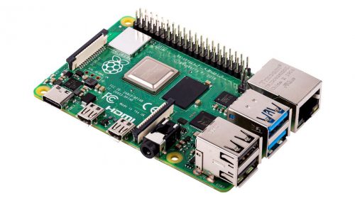
Raspberry Pi 4
For example – I can run VS Code on my MacBook Pro, and connect remotely to a Raspberry Pi 4 that is running headless. I can access the Raspberry Pi file system, run commands on a terminal connected to it, access whatever hardware my Raspberry Pi has, and debug on it.
Remote SSH needs a Raspberry Pi 3 or 4. It is not supported on older Raspberry Pis, or on Raspberry Pi Zero.
Set up remote development on Raspberry Pi
For remote development, your Raspberry Pi needs to be connected to your network either by ethernet or WiFi, and have SSH enabled. The Raspberry Pi documentation has a great article on setting up a headless Raspberry Pi if you don’t already know how to do this.
You also need to know either the IP address of the Raspberry Pi, or its hostname. If you don’t know how to do this, it is also covered in the Raspberry Pi documentation.
Connect to the Raspberry Pi from VS Code
Once the Raspberry Pi is set up, you can connect from VS Code on your Mac or PC.
First make sure you have VS Code installed. If not, you can install it from the VS Code downloads page.
From inside VS Code, you will need to install the Remote SSH extension. Select the Extensions tab from the sidebar menu, then search for Remote development. Select the Remote Development extension, and select the Install button.
Next you can connect to your Raspberry Pi. Launch the VS Code command palette using Ctrl+Shift+P on Linux or Windows, or Cmd+Shift+P on macOS. Search for and select Remote SSH: Connect current window to host (there’s also a connect to host option that will create a new window).
Enter the SSH connection details, using user@host. For the user, enter the Raspberry Pi username (the default is pi). For the host, enter the IP address of the Raspberry Pi, or the hostname. The hostname needs to end with .local, so if you are using the default hostname of raspberrypi, enter raspberrypi.local.
The .local syntax is supported on macOS and the latest versions of Windows or Linux. If it doesn’t work for you then you can install additional software locally to add support. On Linux, install Avahi using the command sudo apt-get install avahi-daemon. On Windows, install either Bonjour Print Services for Windows, or iTunes for Windows.
For example, to connect to my Raspberry Pi 400 with a hostname of pi-400 using the default pi user, I enter pi@pi-400.local.
The first time you connect, it will validate the fingerprint to ensure you are connecting to the correct host. Select Continue from this dialog.
Enter your Raspberry Pi’s password when promoted. The default is raspberry, but you should have changed this (really, you should!).
VS Code will then install the relevant tools on the Raspberry Pi and configure the remote SSH connection.
Code!
You will now be all set up and ready to code on your Raspberry Pi. Start by opening a folder or cloning a git repository and away you go coding, debugging and deploying your applications.
In the remote session, not all extensions you have installed locally will be available remotely. Any extensions that change the behavior of VS Code as an application, such as themes or tools for managing cloud resources, will be available.
Things like language packs and other programming tools are not installed in the remote session, so you’ll need to re-install them. When you install these extensions, you’ll see the Install button has changed to Install in SSH:< hostname > to show it’s being installed remotely.
VS Code may seem daunting at first – it’s a powerful tool with a huge range of extensions. The good news is Microsoft has you covered with lots of hands-on, self-guided learning guides on how to use it with different languages and development tools, from using Git version control, to developing web applications. There’s even a guide to learning Python basics with Wonder Woman!
When we heard that James Dawson had rescued a load of well-worn Raspberry Pi 1 Model B and Model A computers from eBay, refurbished them, and sold them on, we felt warm and fuzzy knowing that some of our oldest devices would be finding new homes.
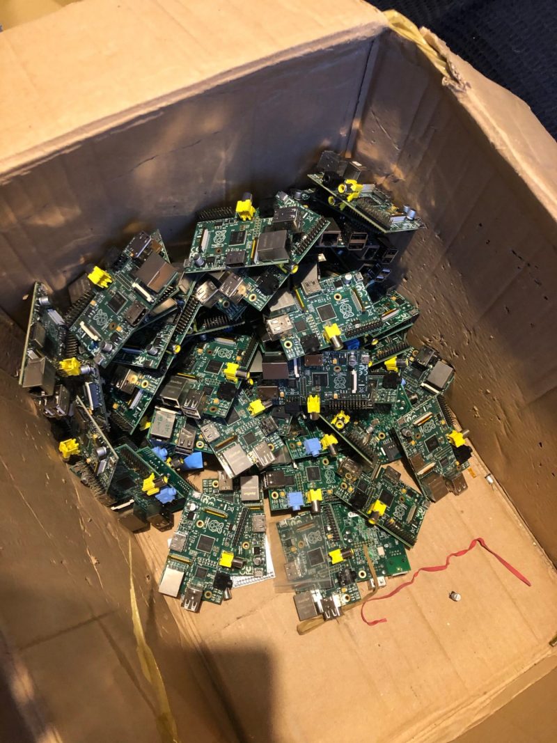
Raspberry Pis in need of new SD card slots. These are now all repaired but yet to be sold
But the feels really hit when we learned that James is donating the money from those resales to us for our Learn at Home campaign, where we get Raspberry Pis into the hands of UK young people who need them the most.
We decided to learn a little more about the guy behind this generous idea.
Where do your computer repair skills come from?
I’m a 25-year-old guy from Newcastle Upon Tyne. I’ve always been into computers and started weekend work experience in a computer repair shop, which turned into an apprenticeship and then a full-time job, giving me a basic knowledge of board-level repairs and hardware diagnostics.
Why Raspberry Pi?
Around the time the first Raspberry Pi (the Model B) came out in 2012, the company I worked for took on a large client in their business IT support division that ran Linux based servers. I immediately purchased a Raspberry Pi and set about learning my way around the Linux terminal and picked it up pretty quickly.
Looking good for your age there, Model A
What do you do now?
I ended up supporting the aforementioned Linux-based servers for several years before moving on. Seven years later I’m a Senior Linux System Administrator / Platform engineer for a multinational company, and I’m not sure I’d be in this position if it wasn’t for Raspberry Pi!
How did the idea to refurbish old Raspberry Pi units come about?
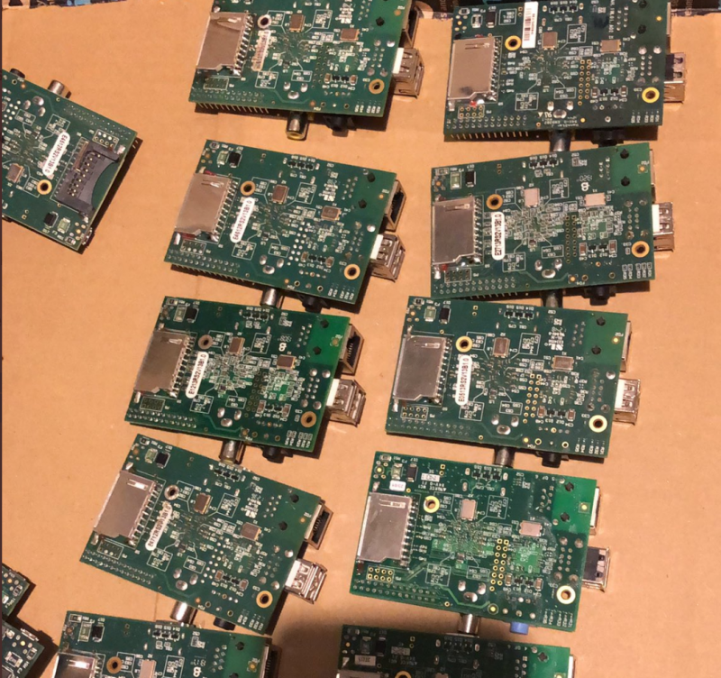
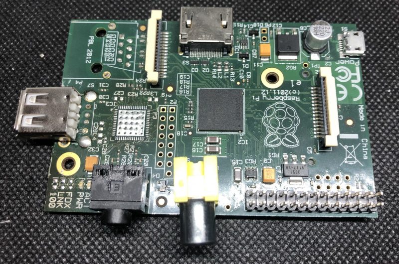
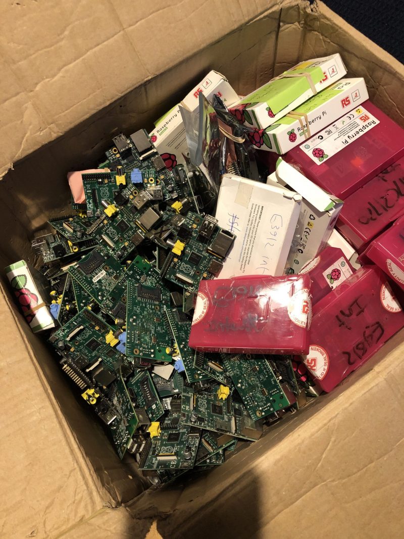
This isn’t something I had planned to do, it just happened! I was looking for some Raspberry Pi accessories on eBay one night, when I came across a box of 200+ broken Raspberry Pis. I had to have them and save them from becoming e-waste, but I didn’t have a plan for them, or even know if they were in a fixable state.
James’ eBay haul
How did you fix them?
Once I found out the condition and performed some diagnostics, I realised that well over half of them were repairable. Using a cheap 3.5″ TFT Raspberry Pi display and a hacky bash script, I created a diagnostic tool that tested the USB ports, Ethernet port, and display output.
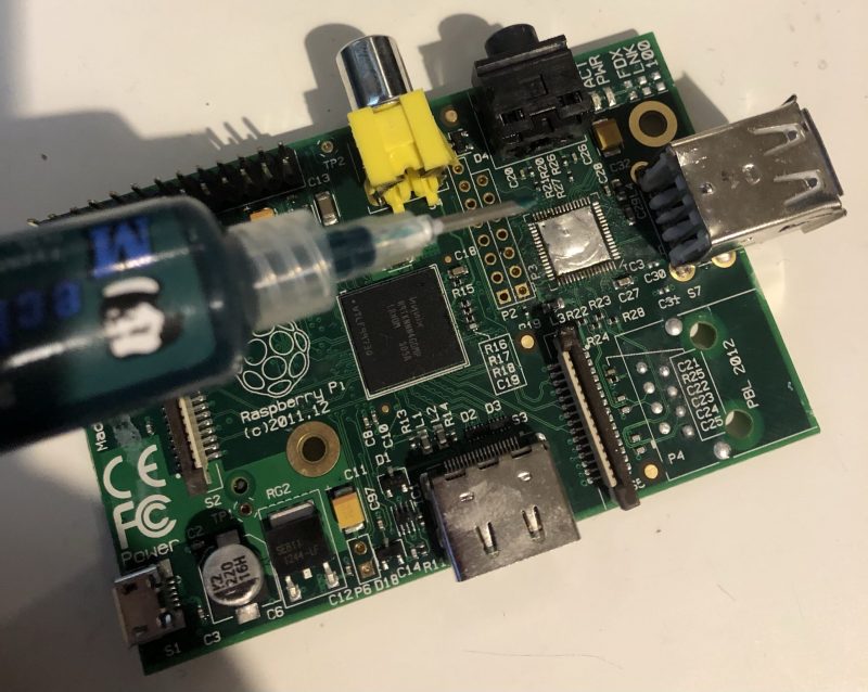
Solder masks are a core component in James’s beauty routine. This photo comes from Part 3 of his five-part project blog.
The technical side of the repairs are detailed in a five-part (so far) blog. Get started on Part 1.
What made you want to donate to the Raspberry Pi Foundation?
I initially decided to see if I could donate the refurbished units to schools or maker spaces, but it turns out donating seven-year-old hardware is harder than it sounds!
Thankfully, there are still a lot of people out there who are interested in early Raspberry Pi models, so I decided to sell them and donate the money. The Raspberry Pi Foundation, specifically their Learn at Home campaign, stood out to me.
How well did they sell?
The first batch I repaired sold out in two days. That raised £400, which has already been donated. I hope to raise around £800 in total, and the next batch will be listed for sale soon.
Refurbished Raspberry Pi Model B, ready to ship
Keep up with James’s tech projects on his blog, or follow him on Twitter.
Since last summer, we’ve been distributing free Raspberry Pi computers to young people in the UK who don’t have access to a computer at home to do their schoolwork.The £800 that James is raising will allow us to give four disadvantaged young people free Raspberry Pi computer kits and ongoing support so they can continue learning while at home during the pandemic.
Do you remember the Danger Shed? New Orleans-based Raspberry Pi-powered home brewing monitoring set up in a… shed? Well, Patrick Murphy and his brewing crew are back with a new toy.
How does it work?
What is it?
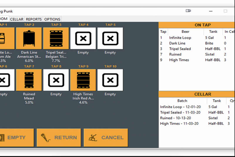
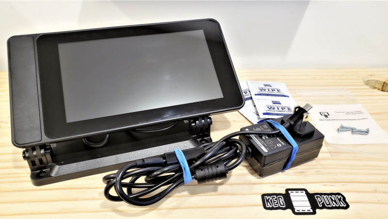
It’s called Keg Punk – inventory software written in Python, specifically for running on Raspberry Pi and the 7″ Raspberry Pi Touch Display. You mount the touchscreen station in a convenient place and run the program on an embedded Raspberry Pi 4.
Nice clean interface
Keg Punk is written in Python and is about 2500 lines of code. Since the program is small with a simple interface, it runs on anything from Raspberry Pi Zero to Raspberry Pi 4.
Who needs it?
As a manager at a local craft brewery, Patrick hated not knowing (or not being able to remember) how many kegs of each beer were left in the cellar.
So he started developing a cellar inventory program with the intention of being able to run it within arm’s reach of the beer taps.
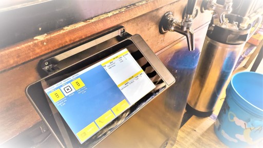
Small enough to sit discreetly next to the beer taps behind the bar
The station needed to have a touchscreen and be tough enough to cope with harsh environments (beer gets EVERYWHERE). Raspberry Pi is the perfect platform for the job as it’s small and easy to connect a touchscreen to.
It can be mounted discreetly close to workstations, so bartenders can quickly see how much stock is left without needing to go down to the cellar.
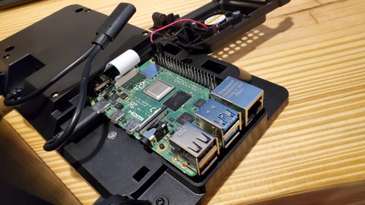
Everything fits neatly behind the Raspberry Pi Touch Display
While requirements in a professional setting inspired the idea of Keg Punk, it was developed with the home brewer in mind. The touchscreen station can easily be mounted to a kegerator (a portmanteau of keg and refrigerator) and the tap display can be configured to your setup.
Three installation options
One of the things the Danger Shed team admire most about Raspberry Pi users is their willingness to do a little hands-on tinkering. With that in mind, they launched Keg Punk in three packages, so you can choose an option based on how much of that you’d like to do:
The Taproom Package
The Taproom Package: This is a full plug-in-and-go setup for those who don’t have a Raspberry Pi or who simply do not have time to tinker while also running a bar.
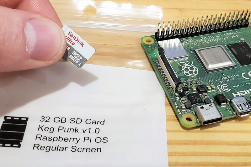
Keg Punk pre-loaded SD card: Perfect for beer slingers who already have a Raspberry Pi but don’t want to install on their current SD card or deal with the hassle of installation.
Keg Punk software only: If you already have a Raspberry Pi and don’t mind a fair bit of tinkering, you can download the Keg Punk software and manually install.
Microsoft’s Visual Studio Code is an excellent C development environment, and now it’s an easy install on Raspberry Pi. Here’s Jim Bennett from Microsoft to show you all how to get VS Code up and running on our tiny computer. Take it away, Jim…
There are a few products in the tech sphere that get me really excited. One of them is Raspberry Pi (obviously), and the other is Visual Studio Code or VS Code. I always hoped that the two would come together one day — and now, to my great pleasure, they have!
VS Code is a free, open source developer text editor originally released for Windows, macOS and x64 Linux. Out of the box it supports generic text editing and git source code control, as well as full web development with JavaScript, TypeScript and Node.js, with debugging, intellisense and all the goodness you’d expect from a full-featured IDE. What makes it super powerful is extensions — bringing a huge range of programming languages, developer tools and other capabilities.
For example my VS Code setup includes a Python extension so I can code and debug in Python, a set of Microsoft Azure extensions so I can manage my cloud services, PlatformIO to allow me to program micro-controllers like Arduino boards coupled with a C++ extension to support coding in C and C++, and even some Docker support. Not a bad setup for a completely free developer tool.
Jim’s Raspberry Pi 400 running VS Code
I’ve been hoping for years VS Code would come to Raspberry Pi, and finally it’s here. As well as supporting Debian Linux on x64, there are now builds for ARM and ARM64 – both of which can run on Raspberry Pi OS (the ARM build on Raspberry Pi OS, the ARM64 on the beta of the 64-bit Raspberry Pi OS). And yes — I am writing this right now on a Raspberry Pi 400 running VS Code!
Why am I so excited about this?
Well, there are a couple of reasons.
Firstly, it brings an exceptional developer tool to Raspberry Pi. There are already some great editors, but nothing of the calibre of VS Code. I can take my $35 computer, plug it into a keyboard and mouse, connect a monitor and a TV and code in a wide range of languages from the same place.
I see kids learning Python at school using one tool, then learning web development in an after-school coding club with a different tool. They can now do both in the same application, reducing the cognitive load – they only have to learn one tool, one debugger, one setup. Combine this with the new Raspberry Pi 400 and you have an all-in-one solution to learning to code, reminiscent of my ZX Spectrum of decades ago, but so much more powerful.
The second reason is to me the most important — it allows kids to share the same development environment as their grown-ups. Imagine the joy of a 10-year-old coding Python using VS Code on their Raspberry Pi plugged into the family TV, then seeing their Mum working from home coding Python in exactly the same tool on her work laptop as part of her job as an AI engineer or data scientist. It also makes it easier when Mum has to inevitably help with unblocking the issues that always come up with learners.
As a young child it was mind-blowing when my Dad brought home a work PC so he could write reports and I could use it to write up my school work – I was using what Dad used at work, making me feel important. I see this with my seven-year-old daughter, seeing her excitement that I use Microsoft Teams for work, the same as she uses for her virtual schooling (she’s even offered to teach me how to use it if I get stuck). To be able to bring that unadulterated joy of using ‘grown-up tools’ to our young learners is priceless.
Installing VS Code
The great news is VS Code is now available as part of the Raspberry Pi OS apt packages. Launch the Raspberry Pi Terminal and run the following commands:
This will download and install VS Code. If you’ve got your hands on a Pico, then you may not even need to do this – VS Code is installed as part of the Pico setup from the Getting Started guide.
After installing VS Code, you can run it from the Programming folder in the Raspberry Pi menu.
Getting started with VS Code
VS Code may seem daunting at first – it’s a powerful tool with a huge range of extensions. The good news is Microsoft has you covered with lots of hands-on, self-guided learning guides on how to use it with different languages and development tools, from using Git version control, to developing web applications — there’s even a guide to learning Python basics with Wonder Woman.
Go grab it and happy coding!
There he is – that’s the real life Jim!
Brilliant Jim Bennett shares loads of Raspberry Pi builds and tutorials over on Expecting Someone Geekier and tweets @jimbobbennett. He also works in Developer Relations at Microsoft. You can learn pretty much everything there is to know about him on github.
One of our engineers, David Plowman, describes machine learning and shares news of a Raspberry Pi depth estimation challenge run by ETH Zürich (Swiss Federal Institute of Technology).
Spoiler alert – it’s all happening virtually, so you can definitely make the trip and attend, or maybe even enter yourself.
What is Machine Learning?
Machine Learning (ML) and Artificial Intelligence (AI) are some of the top engineering-related buzzwords of the moment, and foremost among current ML paradigms is probably the Artificial Neural Network (ANN).
They involve millions of tiny calculations, merged together in a giant biologically inspired network – hence the name. These networks typically have millions of parameters that control each calculation, and they must be optimised for every different task at hand.
This process of optimising the parameters so that a given set of inputs correctly produces a known set of outputs is known as training, and is what gives rise to the sense that the network is “learning”.
A popular type of ANN used for processing images is the Convolutional Neural Network. Many small calculations are performed on groups of input pixels to produce each output pixel
Machine Learning frameworks
A number of well known companies produce free ML frameworks that you can download and use on your own computer. The network training procedure runs best on machines with powerful CPUs and GPUs, but even using one of these pre-trained networks (known as inference) can be quite expensive.
One of the most popular frameworks is Google’s TensorFlow (TF), and since this is rather resource intensive, they also produce a cut-down version optimised for less powerful platforms. This is TensorFlow Lite(TFLite), which can be run effectively on Raspberry Pi.
Depth estimation
ANNs have proven very adept at a wide variety of image processing tasks, most notably object classification and detection, but also depth estimation. This is the process of taking one or more images and working out how far away every part of the scene is from the camera, producing a depth map.
Here’s an example:
The image on the right shows, by the brightness of each pixel, how far away the objects in the original (left-hand) image are from the camera (darker = nearer).
We distinguish between stereo depth estimation, which starts with a stereo pair of images (taken from marginally different viewpoints; here, parallax can be used to inform the algorithm), and monocular depth estimation, working from just a single image.
The applications of such techniques should be clear, ranging from robots that need to understand and navigate their environments, to the fake bokeh effects beloved of many modern smartphone cameras.
Depth Estimation Challenge
We were very interested then to learn that, as part of the CVPR (Computer Vision and Pattern Recognition) 2021 conference, Andrey Ignatov and Radu Timofte of ETH Zürich were planning to run a Monocular Depth Estimation Challenge. They are specifically targeting the Raspberry Pi 4 platform running TFLite, and we are delighted to support this effort.
For more information, or indeed if any technically minded readers are interested in entering the challenge, please visit:
The conference and workshops are all taking place virtually in June, and we’ll be sure to update our blog with some of the results and models produced for Raspberry Pi 4 by the competing teams. We wish them all good luck!
In the latest issue of The MagPi Magazine, Alasdair Allan shares the secrets he had to keep while working behind the scenes to get Raspberry Pi’s RP2040 chip out into the world.
BEST friends
There is a new thing in the world, and I had a ringside seat for its creation.
For me, it started just over a year ago with a phone call from Eben Upton. One week later I was sitting in a meeting room at Raspberry Pi Towers in Cambridge, my head tilted to one side while Eben scribbled on a whiteboard and waved his hands around.
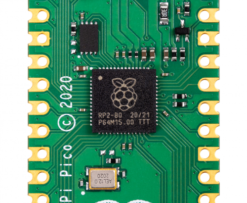
Eben had just told me that Raspberry Pi was designing its own silicon, and he was talking about the chip that would eventually be known as RP2040. Eben started out by drawing the bus fabric, which isn’t where you normally start when you talk about a new chip, but it turned out RP2040 was a rather unusual chip.
“I gradually drifted sideways into playing with the toys.”
I get bored easily. I started my career doing research into the high-energy physics of collision shocks in the accretion discs surrounding white dwarf stars, but I gradually drifted sideways into playing with the toys.
After spending some time working with agent-based systems to solve scheduling problems for robotic telescopes, I became interested in machine learning and what later became known as ‘big data’.
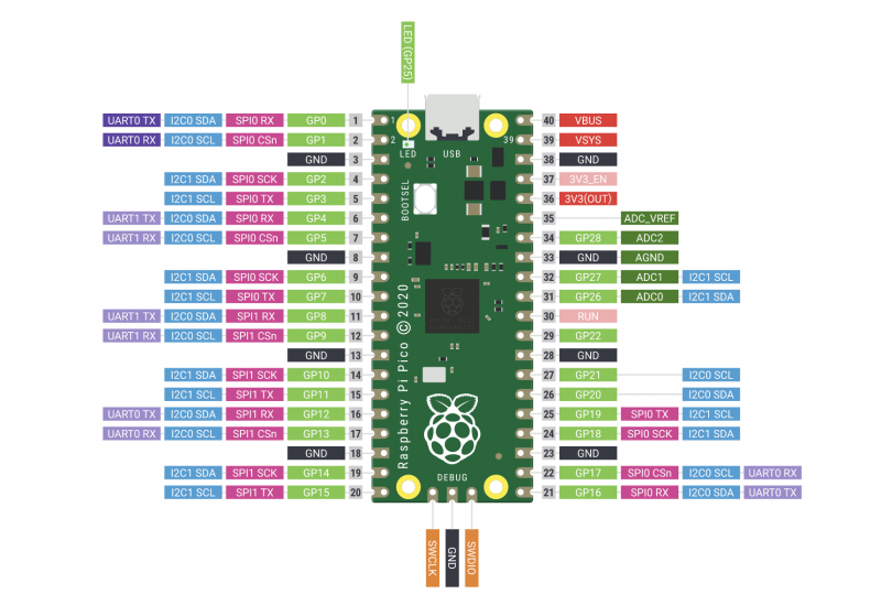
Meet Raspberry Pi Pico
From there, I spent time investigating the ‘data exhaust’ and data living outside the cloud in embedded and distributed devices, and as a consequence did a lot of work on mobile systems. Which led me to do some of the thinking, and work, on what’s now known as the Internet of Things. Which meant I had recently spent a lot of time writing and talking about embedded hardware.
Eben was looking for someone to make sure the documentation around Raspberry Pi Pico, and RP2040 silicon itself, was going to measure up. I took the job.
Rumour mill
I had spent the previous six months benchmarking Machine Learning (ML) inferencing on embedded hardware, and a lot of time writing and talking about the trendy new world of Tiny ML.
What is a microcontroller?
The rumours of what I was going to be doing for Raspberry Pi started flying on social media almost immediately. The somewhat pervasive idea that I was there to help support putting a Coral Edge TPU onto Raspberry Pi 5 was a particularly good wheeze.
Instead, I was going to spend the next year metaphorically locked in a room building a documentation toolchain around – and of course writing about – a totally secret product.
I couldn’t talk about it in public, and I talk about things in public a lot. Only the fact that almost everyone else spent the next year locked indoors as well kept too many questions from being asked. I didn’t have to tell conference organisers that I couldn’t talk about what I was doing, because there weren’t any conferences to organise.
I’m rather pleased with what I’ve done with my first year at Raspberry Pi, and of course with how my work on RP2040 and Raspberry Pi Pico turned out.
Much like a Raspberry Pi is an accessible computer that gives you everything you need to learn to write a program, RP2040 is an accessible chip with everything you need to learn to build a product. It’s going to bring a big change to the microcontroller market, and I’m really rather pleased I got a ringside seat to its creation.
Today, I discuss the second research seminar in our series of six free online research seminars focused on diversity and inclusion in computing education, where we host researchers from the UK and USA together with the Royal Academy of Engineering. By diversity, we mean any dimension that can be used to differentiate groups and people from one another. This might be, for example, age, gender, socio-economic status, disability, ethnicity, religion, nationality, or sexuality. The aim of inclusion is to embrace all people irrespective of difference.
In this seminar, we were delighted to hear from Prof Tia Madkins (University of Texas at Austin), Dr Nicol R. Howard (University of Redlands), and Shomari Jones (Bellevue School District) (find their bios here), who talked to us about culturally responsive pedagogy and equity-focused teaching in K-12 Computer Science.
Prof Tia Madkins
Dr Nicol R. Howard
Shomari Jones
Equity-focused computer science teaching
Tia began the seminar with an audience-engaging task: she asked all participants to share their own definition of equity in the seminar chat. Amongst their many suggestions were “giving everybody the same opportunity”, “equal opportunity to access high-quality education”, and “everyone has access to the same resources”. I found Shomari’s own definition of equity very powerful:
“Equity is the fair treatment, access, opportunity, and advancement of all people, while at the same time striving to identify and eliminate barriers that have prevented the full participation of some groups. Improving equity involves increasing justice and fairness within the procedures and processes of institutions or systems, as well as the distribution of resources. Tackling equity requires an understanding of the root cause of outcome disparity within our society.”
Shomari Jones
This definition is drawn directly from the young people Shomari works with, and it goes beyond access and opportunity to the notion of increasing justice and fairness and addressing the causes of outcome disparity. Justice was a theme throughout the seminar, with all speakers referring to the way that their work looks at equity in computer science education through a justice-oriented lens.
Removing deficit thinking
Using a justice-oriented approach means that learners should be encouraged to use their computer science knowledge to make a difference in areas that are important to them. It means that just having access to a computer science education is not sufficient for equity.
Tia spoke about the need to reject “deficit thinking” (i.e. focusing on what learners lack) and instead focus on learners’ strengths or assets and how they bring these to the school classroom. For researchers and teachers to do this, we need to be aware of our own mindset and perspective, to think about what we value about ethnic and racial identities, and to be willing to reflect and take feedback.
Activities to support computer science teaching
Nicol talked about some of the ways of designing computing lessons to be equity-focused. She highlighted the benefits of pair programming and other peer pedagogies, where students teach and learn from each other through feedback and sharing ideas/completed work. She suggested using a variety of different programs and environments, to ensure a range of different pathways to understanding. Teachers and schools can aim to base teaching around tools that are open and accessible and, where possible, available in many languages. If the software environment and tasks are accessible, they open the doors of opportunity to enable students to move on to more advanced materials. To demonstrate to learners that computer science is applicable across domains, the topic can also be introduced in the context of mathematics and other subjects.
Learners can benefit from learning computer science regardless of whether they want to become a computer scientist. Computing offers them skills that they can use for self-expression or to be creative in other areas of their life. They can use their knowledge for a specific purpose and to become more autonomous, particularly if their teacher does not have any deficit thinking. In addition, culturally relevant teaching in the classroom demonstrates a teacher’s deliberate and explicit acknowledgment that they value all students in their classroom and expect students to excel.
Engaging family and community
Shomari talked about the importance of working with parents and families of ethnically diverse students in order to hear their voices and learn from their experiences.
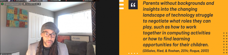
He described how the absence of a background in technology of parents and carers can drastically impact the experiences of young people.
“Parents without backgrounds and insights into the changing landscape of technology struggle to negotiate what roles they can play, such as how to work together in computing activities or how to find learning opportunities for their children.”
Shomari drew on an example from the Pacific Northwest in the US, a region with many successful technology companies. In this location, young people from wealthy white and Asian communities can engage fully in informal learning of computer science and can have aspirations to enter technology-related fields, whereas amongst the Black and Latino communities, there are significant barriers to any form of engagement with technology. This already existent inequity has been enhanced by the coronavirus pandemic: once so much of education moved online, it became widely apparent that many families had never owned, or even used, a computer. Shomari highlighted the importance of working with pre-service teachers to support them in understanding the necessity of family and community engagement.
Building classroom communities
Building a classroom community starts by fostering and maintaining relationships with students, families, and their communities. Our speakers emphasised how important it is to understand the lives of learners and their situations. Through this understanding, learning experiences can be designed that connect with the learners’ lived experiences and cultural practices. In addition, by tapping into what matters most to learners, teachers can inspire them to be change agents in their communities. Tia gave the example of learning to code or learning to build an app, which provides learners with practical tools they can use for projects they care about, and with skills to create artefacts that challenge and document injustices they see happening in their communities.
Find out more
If you want to learn more about this topic, a great place to start is the recent paper Tia and Nicol have co-authored that lays out more detail on the work described in the seminar: Engaging Equity Pedagogies in Computer Science Learning Environments, by Tia C. Madkins, Nicol R. Howard and Natalie Freed, 2020.
Once you’ve signed up, we’ll email you the seminar meeting link and instructions for joining. If you attended Peter’s and Billy’s seminar, the link remains the same.
When I first joined Raspberry Pi as a software engineer four and a half years ago, I didn’t know anything about chip design. I thought it was magic. This blog post looks at the journey to Raspberry Silicon and the design process of RP2040.
RP2040 – the heart of Raspberry Pi Pico
RP2040 has been in development since summer 2017. Chips are extremely complicated to design. In particular, the first chip you design requires you to design several fundamental components, which you can then reuse on future chips. The engineering effort was also diverted at some points in the project (for example to focus on the Raspberry Pi 4 launch).
Once the chip architecture is specified, the next stage of the project is the design and implementation, where hardware is described using a hardware description language such as Verilog. Verilog has been around since 1984 and, along with VHDL, has been used to design most chips in existence today. So what does Verilog look like, and how does it compare to writing software?
Suppose we have a C program that implements two wrapping counters:
This C program will execute sequentially line by line, and the processor won’t be able to do anything else (unless it is interrupted) while running this code. Let’s compare this with a Verilog implementation of the same counter:
Verilog statements are executed in parallel on every clock cycle, so both i and j are updated at exactly the same time, whereas the C program increments i first, followed by j. Expanding on this idea, you can think of a chip as thousands of small Verilog modules like this, all executing in parallel.
A chip designer has several tools available to them to test the design. Testing/verification is the most important part of a chip design project: if a feature hasn’t been tested, then it probably doesn’t work. Two methods of testing used on RP2040 are simulators and FPGAs.
A simulator lets you simulate the entire chip design, and also some additional components. In RP2040’s case, we simulated RP2040 and an external flash chip, allowing us to run code from SPI flash in the simulator. That is the beauty of hardware design: you can design some hardware, then write some C code to test it, and then watch it all run cycle by cycle in the simulator.
“ell” from the phrase “Hello World” from core0 of RP2040 in a simulator
The downside to simulators is that they are very slow. It can take several hours to simulate just one second of a chip. Simulation time can be reduced by testing blocks of hardware in isolation from the rest of the chip, but even then it is still slow. This is where FPGAs come in…
FPGAs (Field Programmable Gate Arrays) are chips that have reconfigurable logic, and can emulate the digital parts of a chip, allowing most of the logic in the chip to be tested.
FPGAs can’t emulate the analogue parts of a design, such as the resistors that are built into RP2040’s USB PHY. However, this can be approximated by using external hardware to provide analogue functionality. FPGAs often can’t run a design at full speed. In RP2040’s case, the FPGA was able to run at 48MHz (compared to 133MHz for the fully fledged chip). This is still fast enough to test everything we wanted and also develop software on.
FPGAs also have debug logic built into them. This allows the hardware designer to probe signals in the FPGA, and view them in a waveform viewer similar to the simulator above, although visibility is limited compared to the simulator.
Graham’s tidy FPGAGraham’s less tidy FPGAOh dear
The RP2040 bootrom was developed on FPGA, allowing us to test the USB boot mode, as well executing code from SPI flash. In the image above, the SD card slot on the FPGA is wired up to SPI flash using an SD card-shaped flash board designed by Luke Wren.
USB testing on FPGA
In parallel to Verilog development, the implementation team is busy making sure that the Verilog we write can actually be made into a real chip. Synthesis takes a Verilog description of the chip and converts the logic described into logic cells defined by your library choice. RP2040 is manufactured by TSMC, and we used their standard cell library.
RP2040 silicon in a DIL package!
Chip manufacturing isn’t perfect. So design for test (DFT) logic is inserted, allowing the logic in RP2040 to be tested during production to make sure there are no manufacturing defects (short or open circuit connections, for example). Chips that fail this production test are thrown away (this is a tiny percentage – the yield for RP2040 is particularly high due to the small die size).
After synthesis, the resulting netlist goes through a layout phase where the standard cells are physically placed and interconnect wires are routed. This is a synchronous design so clock trees are inserted, and timing is checked and fixed to make sure the design meets the clock speeds that we want. Once several design rules are checked, the layout can be exported to GDSII format, suitable for export to TSMC for manufacture.
RP2040 chips ready for a bring up board
(In reality, the process of synthesis, layout, and DFT insertion is extremely complicated and takes several months to get right, so the description here is just a highly abbreviated overview of the entire process.)
Once silicon wafers are manufactured at TSMC they need to be put into a package. After that, the first chips are sent to Pi Towers for bring-up!
The RP2040 bring-up board
A bring-up board typically has a socket (in the centre) so you can test several chips in a single board. It also separates each power supply on the chip, so you can limit the current on first power-up to check there are no shorts. You don’t want the magic smoke to escape!
The USB boot mode working straight out of the box on a bring-up board!
Once the initial bring-up was done, RP2040 was put through its paces in the lab. Characterising behaviour, seeing how it performs at temperature and voltage extremes.
Once the initial batch of RP2040s are signed off we give the signal for mass production, ready for them to be put onto Pico boards that you have in your hands today.
82K RP2040s ready for shipment to Sony
A chip is useless without detailed documentation. While RP2040 was making its way to mass production, we spent several months writing the SDK and excellent documentation you have available to you today.