The Raspberry Pi Foundation and ESA Education are excited to announce that 214 teams participating in Mission Space Lab of this year’s European Astro Pi Challenge have achieved Flight Status. That means they will have their computer programs run on the International Space Station (ISS) later this month!
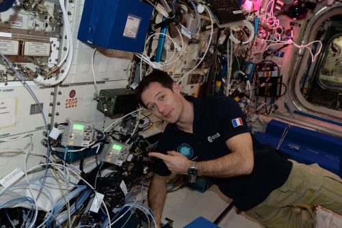
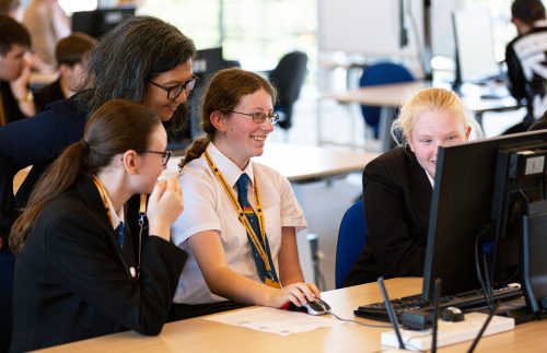
ESA Astronaut Thomas Pesquet with the Astro Pi computers onboard the ISS
Mission Space Lab gives teams of students and young people up to 19 years of age the amazing opportunity to conduct scientific experiments aboard the ISS, by writing code for the Astro Pi computers — Raspberry Pi computers augmented with Sense HATs. Teams can choose between two themes for their experiments, investigating either life in space or life on Earth.
Life in space
For ‘Life in space’ experiments, teams use the Astro Pi computer known as Ed to investigate life inside the Columbus module of the ISS. For example, past teams have:
Used the Astro Pi’s accelerometer sensor to compare the motion of the ISS during normal flight compared to its motion during course corrections and reboost manoeuvres
Investigated whether influenza is transmissible on a spacecraft such as the ISS
Monitored pressure inside the Columbus module to be able to warn the astronauts on board of space debris or micrometeoroids colliding with the station
And much more
Compilation of photographs of Earth, taken by Astro Pi Izzy aboard the ISS
Life on Earth
In ‘Life on Earth’ experiments, teams investigate life on our home planet’s surface using the Astro Pi computer known as Izzy. Izzy’s near-infrared camera (with a blue optical filter) faces out of a window in the ISS and is pointed at Earth. For example, past teams have:
Investigated variations in Earth’s magnetic field
Used machine learning to identify geographical areas that had recently suffered from wildfires
Studied climate change based on coastline erosion over the past 30 years
And much besides
Phase 1 and 2 of Mission Space Lab
In Phase 1 of Mission Space Lab, teams only have to submit an experiment idea. Our team then judges the teams’ ideas based on their originality, feasibility, and use of hardware. This year, 426 teams submitted experiment ideas, with 396 progressing to Phase 2.
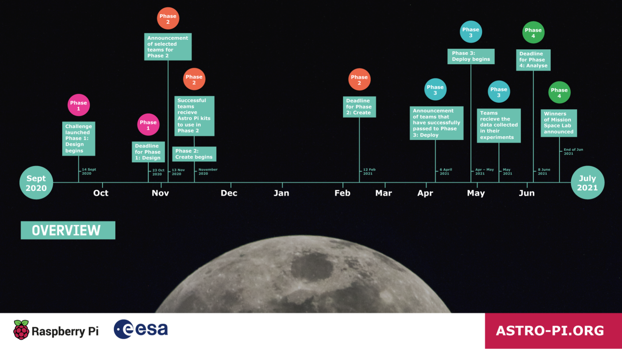
Timeline of Mission Space Lab in 2020/21 — click to enlarge
At the beginning of Phase 2 of the challenge, we send our special Astro Pi kits to the teams to help them write and test their programs. The kits contain hardware that is similar to the Astro Pi computers in space, including a Raspberry Pi 3 Model B, Raspberry Pi Sense HAT, and Raspberry Pi Camera Modules (V2 and NoIR).
Mission Space Lab teams then write the programs for their experiments in Python. Once teams are happy with their programs, have tested them on their Astro Pi kits, and submitted them to us for judging, we run a series of tests on them to ensure that they follow experiment rules and can run without errors on the ISS. The experiments that meet the relevant criteria are then awarded Flight Status.
Phase 3: Flight Status achieved
The 214 teams awarded flight status this year represent 21 countries and 862 young people, with 30% female participants. 137 teams with ‘Life on Earth’ experiments and 77 teams with ‘Life in space’ experiments have successfully made it through to Phase 3.
Spain has the most teams progressing to the next phase (26), closely followed by the UK (25), Romania (21), France (21) and Greece (18).
In the next few weeks, the teams’ experiments will be deployed to the Astro Pi computers on the ISS, and most of them will run overseen by ESA Astronaut Thomas Pesquet, who is going to fly to the ISS on 22 April on his new mission, Alpha.
In the final phase, we’ll send the teams the data their experiments collect, to analyse and write short reports about their findings. Based on these reports, we and the ESA Education experts will determine the winner of this year’s Mission Space Lab. The winning and highly commended teams will receive special prizes. Last year’s outstanding teams got to take part in a Q&A with ESA astronaut Luca Parmitano!
Well done to everyone who has participated, and congratulations to all the successful teams. We are really looking forward to reading your reports!
Traverse a crumbly cavern in our homage to a Spectrum classic. Mark Vanstone has the code
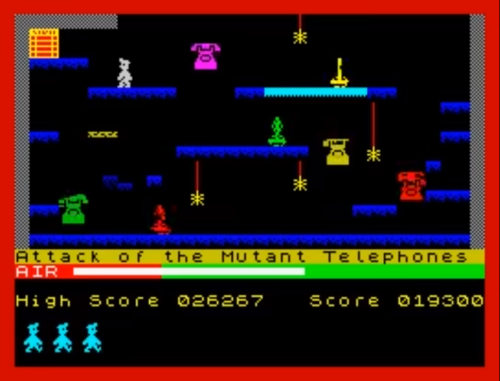
One of the most iconic games on the Sinclair ZX Spectrum featured a little man called Miner Willy, who spent his days walking and jumping from platform to platform collecting the items needed to unlock the door on each screen. Manic Miner’s underground world featured caverns, processing plants, killer telephones, and even a forest featuring little critters that looked suspiciously like Ewoks.
Written by programmer Matthew Smith and released by Bug-Byte in 1983, the game became one of the most successful titles on the Spectrum. Smith was only 16 when he wrote Manic Miner and even constructed his own hardware to speed up the development process, assembling the code on a TRS-80 and then downloading it to the Spectrum with his own hand-built interface. The success of Manic Miner was then closely followed by Jet Set Willy, featuring the same character, and although they were originally written for the Spectrum, the games very soon made it onto just about every home computer of the time.
Miner Willy makes his way to the exit, avoiding those vicious eighties telephones.
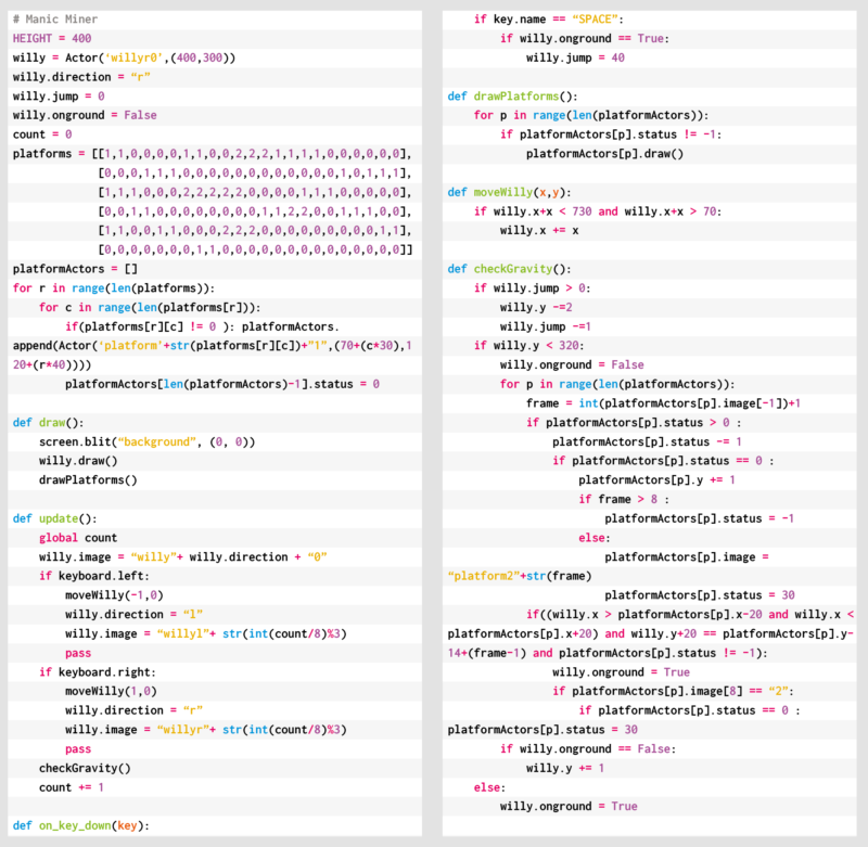
Both Manic Miner and Jet Set Willy featured unstable platforms which crumbled in Willy’s wake, and it’s these we’re going to try to recreate this month. In this Pygame Zero example, we need three frames of animation for each of the two directions of movement. As we press the arrow keys we can move the Actor left and right, and in this case, we’ll decide which frame to display based on a count variable, which is incremented each time our update() function runs. We can create platforms from a two-dimensional data list representing positions on the screen with 0 meaning a blank space, 1 being a solid platform, and 2 a collapsible platform. To set these up, we run through the list and make Actor objects for each platform segment.
For our draw() function, we can blit a background graphic, then Miner Willy, and then our platform blocks. During our update() function, apart from checking key presses, we also need to do some gravity calculations. This will mean that if Willy isn’t standing on a platform or jumping, he’ll start to fall towards the bottom of the screen. Instead of checking to see if Willy has collided with the whole platform, we only check to see if his feet are in contact with the top. This means he can jump up through the platforms but will then land on the top and stop. We set a variable to indicate that Willy’s standing on the ground so that when the SPACE bar is pressed, we know if he can jump or not. While we’re checking if Willy’s on a platform, we also check to see if it’s a collapsible one, and if so, we start a timer so that the platform moves downwards and eventually disappears. Once it’s gone, Willy will fall through. The reason we have a delayed timer rather than just starting the platform heading straight down is so that Willy can run across many tiles before they collapse, but his way back will quickly disappear. The disappearing platforms are achieved by changing the image of the platform block as it moves downward.
As we’ve seen, there were several other elements to each Manic Miner screen, such as roaming bears that definitely weren’t from Star Wars, and those dastardly killer telephones. We’ll leave you to add those.
Here’s Mark’s code for a Manic Miner-style platformer. To get it working on your system, you’ll need to install Pygame Zero. And to download the full code and assets, head here.
Get your copy of Wireframe issue 49
You can read more features like this one in Wireframe issue 49, available directly from Raspberry Pi Press — we deliver worldwide.
And if you’d like a handy digital version of the magazine, you can also download issue 49 for free in PDF format.
Easter is nearly upon us, and we’ll be stepping away from our home-office desks for a few days. Before we go, we thought we’d share some cool Easter-themed projects from the Raspberry Pi community.
Egg-painting robot
Teacher Klaus Rabeder designed, 3D-printed, and built a robot which his students programmed in Python to paint eggs with Easter designs. Each student came up with their own design and then programmed the robot to recreate it. The robot can draw letters and numbers, patterns, and figures (such as an Easter bunny) on an egg, as well as a charming meadow made of randomly calculated blades of grass. Each student took home the egg bearing their unique design.
The machine has three axes of movement: one that rotates the egg, one that moves the pens up and down, and one that makes servo motors put the pen tips onto the egg’s surface. Each servo is connected to two pens. Springs between the servo and pen make sure not too much pressure is applied.
What a cool way to spend your computing lessons!
Digital Easter egg hunt
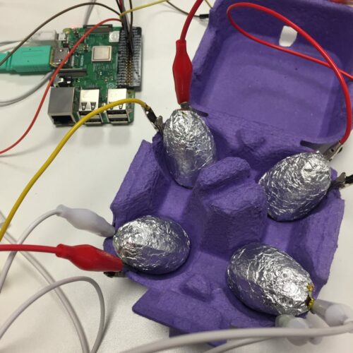
Go digital this Easter
Why hunt for chocolate eggs in a race against time before they melt, when you can go digital? Our very own Alex made this quick and easy game with a Raspberry Pi, a few wires, and some simple code. Simply unwrap your chocolate eggs and rewrap them with the silver side of the foil facing outwards to make them more conductive. The wires create a circuit, and when the circuit is closed with the foil-wrapped egg, the Raspberry Pi reveals the location of a bigger chocolate egg.
All the code and kit you need to recreate this game yourself is here.
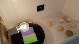
Incubate baby chicks
The second-best thing about this time of year — after all the chocolate — is the cute baby animals. Lambs and bunnies get a special mention, but this project makes sure that chicken eggs are properly incubated to help baby chicks hatch. Maker Dennis Hejselbak added a live-streaming camera so he and other chick fans can keep an eye on things.
We’re sad to report that Emma still hasn’t revised her ‘No office chicks’ policy since we first reported this project back in 2015. Maybe next year?
Happy Easter!
Stand by for a delicious new issue of Wireframe magazine tomorrow. We’ll see you on Tuesday!
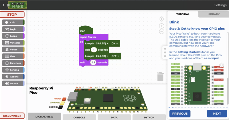
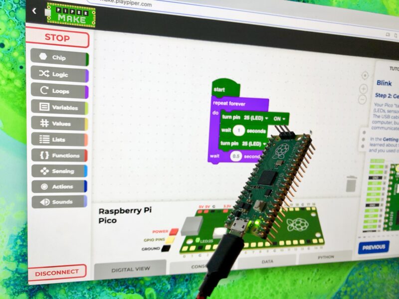
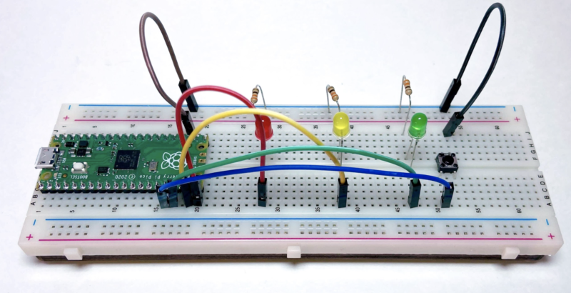
If you already have a Raspberry Pi Pico, you can get started right away
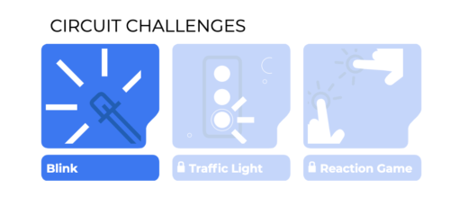
Complete coding challenges with Pico
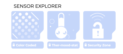
Learn about circuits and sensors as you complete each coding challenge
The block coding environment invites you to try a series of challenges. When you succeed in blinking an LED, the next challenge is opened up to you. New challenges are released every month, and it’s a great way to guide your learning and give you a sense of achievement as you check off each task.
But I don’t have a Pico or the components I need!
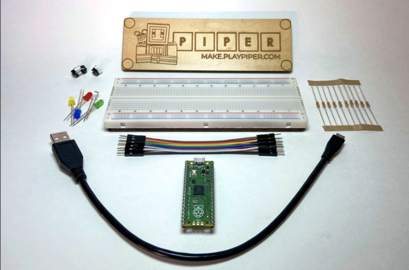
You’re going to need some kit to complete these challenges. The components you’ll need are easy to get hold of, and they’re things you probably already have lying around if you like to tinker, but if you’re a coding newbie and don’t have a workshop full of trinkets, Piper makes it easy for you. You can join their Makers Club and receive a one-off Starter Kit containing a Raspberry Pi Pico, LEDs, resistors, switches, and wires.
The Starter Kit contains everything you need to complete the first challenges
If you sign up to Piper’s Monthly Makers Club you’ll receive the Starter Kit, plus new hardware each month to help you complete the latest challenge. Each Raspberry Pi Pico board ships with Piper Make firmware already loaded, so you can plug and play.
Trying out the traffic light challenge with the Starter Kit
If you already have things like a breadboard, LEDs, and so on, then you don’t need to sign up at all. Dive straight in and get started on the challenges.
I have a Raspberry Pi Pico. How do I play?
A quick tip before we go: when you hit the Piper Make landing page for the first time, don’t click ‘Getting Started’ just yet. You need to set up your Pico first of all, so scroll down and select ‘Setup my Pico’. Once you’ve done that, you’re good to go.
Scroll down on the landing page to set up your Pico before hitting ‘Getting Started’
Pimoroni has brought out two add‑ons with screens: Pico Display and Pico Explorer. A very basic set of methods is provided in the Pimoroni UF2 file.In this article, we aim to explain how the screens are controlled with these low-level instructions, and provide a library of extra routines and example code to help you produce stunning displays.
You don’t have to get creative with your text placement, but you can
You will need to install the Pimoroni MicroPython UF2 file on your Pico and Thonny on your computer.
All graphical programs need the following ‘boilerplate’ code at the beginning to initialise the display and create the essential buffer. (We’re using a Pico Explorer – just change the first line for a Pico Display board.)
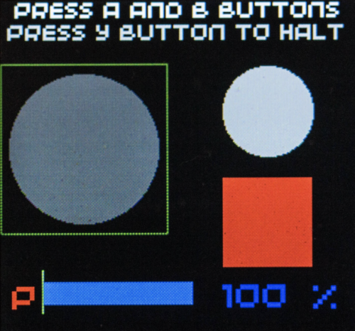
The four buttons give you a way of getting data back from the user as well as displaying information
This creates a buffer with a 16-bit colour element for each pixel of the 240×240 pixel screen. The code invisibly stores colour values in the buffer which are then revealed with a display.update() instruction.
The top-left corner of the screen is the origin (0,0) and the bottom-right pixel is (239,239).
Supplied methods
display.set_pen(r, g, b)
Sets the current colour (red, green, blue) with values in the range 0 to 255.
grey = display.create_pen(100,100,100)
Allows naming of a colour for later use.
display.clear()
Fills all elements in the buffer with the current colour.
display.update()
Makes the current values stored in the buffer visible. (Shows what has been written.)
display.pixel(x, y)
Draws a single pixel with the current colour at point(x, y).
display.rectangle(x, y ,w ,h)
Draws a filled rectangle from point(x, y), w pixels wide and h pixels high.
display.circle(x, y, r)
Draws a filled circle with centre (x, y) and radius r.
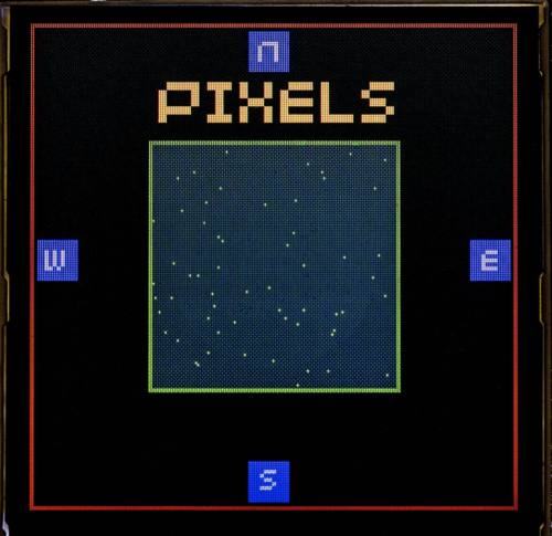
display.character(78, 112, 5 ,2)
Draws character number 78 (ASCII = ‘N’) at point (112,5) in size 2. Size 1 is very small, while 6 is rather blocky.
display.text("Pixels", 63, 25, 200, 4)
Draws the text on the screen from (63,25) in size 4 with text wrapping to next line at a ‘space’ if the text is longer than 200 pixels. (Complicated but very useful.)
display.pixel_span(30,190,180)
Draws a horizontal line 180 pixels long from point (30,190).
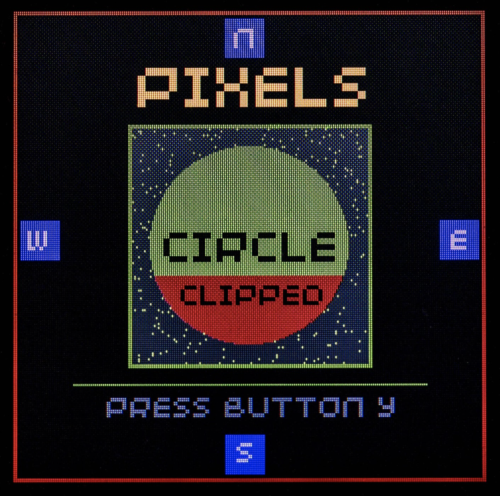
display.set_clip(20, 135, 200, 100)
While the screens are quite small in size, they have plenty of pixels for display
After this instruction, which sets a rectangular area from (20,135), 200 pixels wide and 100 pixels high, only pixels drawn within the set area are put into the buffer. Drawing outside the area is ignored. So only those parts of a large circle intersecting with the clip are effective. We used this method to create the red segment.
display.remove_clip()
This removes the clip.
display.update()
This makes the current state of the buffer visible on the screen. Often forgotten.
if display.is_pressed(3): # Y button is pressed ?
Read a button, numbered 0 to 3.
You can get more creative with the colours if you wish
This code demonstrates the built-in methods and can be downloaded here.
# Pico Explorer - Basics
# Tony Goodhew - 20th Feb 2021
import picoexplorer as display
import utime, random
#Screen essentials
width = display.get_width()
height = display.get_height()
display_buffer = bytearray(width * height * 2)
display.init(display_buffer)
# Named pen colour grey = display.create_pen(100,100,100) # ==== Main ====== blk() title("Pico Explorer Graphics",200,200,0) display.set_pen(255,0,0) display.clear() display.set_pen(0,0,0) display.rectangle(2,2,235,235) show(1) # Blue rectangles display.set_pen(0,0,255) display.rectangle(3,107,20,20) display.rectangle(216,107,20,20) display.rectangle(107,3,20,20) display.rectangle(107,216,20,20) display.set_pen(200,200,200) #Compass points display.character(78,112,5,2) # N display.character(83,113,218,2) # S display.character(87,7,110,2) # W display.character(69,222,110,2) # E show(1) # Pixels display.set_pen(255,255,0) display.text("Pixels", 63, 25, 200, 4) display.set_pen(0,200,0) display.rectangle(58,58,124,124) display.set_pen(30,30,30) display.rectangle(60,60,120,120) display.update() display.set_pen(0,255,0) for i in range(500): xp = random.randint(0,119) + 60 yp = random.randint(0,119) + 60 display.pixel(xp,yp) display.update() show(1) # Horizontal line display.set_pen(0,180,0) display.pixel_span(30,190,180) show(1) # Circle display.circle(119,119,50) show(1.5) display.set_clip(20,135, 200, 100) display.set_pen(200,0,0) display.circle(119,119,50) display.remove_clip()
display.set_pen(0,0,0) display.text("Circle", 76, 110, 194, 3) display.text("Clipped", 85, 138, 194, 2) display.set_pen(grey) # Previously saved colour # Button Y display.text("Press button y", 47, 195, 208, 2) show(0) running = True while running: if display.is_pressed(3): # Y button is pressed ? running = False blk()
# Tidy up title("Done",200,0,0) show(2) blk()
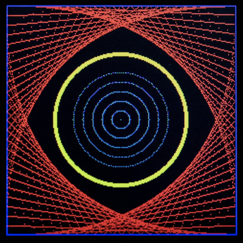
Straight lines can give the appearance of curves
We’ve included three short procedures to help reduce code repetition:
def blk()
This clears the screen to black – the normal background colour.
def show(tt)
This updates the screen, making the buffer visible and then waits tt seconds.
def title(msg,r,g,b)
This is used to display the msg string in size 4 text in the specified colour for two seconds, and then clears the display.
As you can see from the demonstration, we can accomplish a great deal using just these built-in methods. However, it would be useful to be able to draw vertical lines, lines from point A to point B, hollow circles, and rectangles. If these are written as procedures, we can easily copy and paste them into new projects to save time and effort.
You don’t need much to create interesting graphics
In our second demonstration, we’ve included these ‘helper’ procedures. They use the parameters (t, l, r, b) to represent the (top, left) and the (right, bottom) corners of rectangles or lines.
def horiz(l,t,r): # left, top, right
Draws a horizontal line.
def vert(l,t,b): # left, top, bottom
Draws a vertical line.
def box(l,t,r,b): # left, top, right, bottom
Draws an outline rectangular box.
def line(x,y,xx,yy):
Draws a line from (x,y) to (xx,yy).
def ring(cx,cy,rr,rim): # Centre, radius, thickness
Draws a circle, centred on (cx,cy), of outer radius rr and pixel thickness of rim. This is easy and fast but has the disadvantage that it wipes out anything inside ring.
def ring2(cx,cy,r): # Centre (x,y), radius
Draw a circle centred on (cx,cy), of radius rr with a single-pixel width. Can be used to flash a ring around something already drawn on the screen. You need to importmath as it uses trigonometry.
def align(n, max_chars):
This returns a string version of int(n), right aligned in a string of max_chars length. Unfortunately, the font supplied by Pimoroni in its UF2 is not monospaced.
What will you create with your Pico display?
The second demonstration is too long to print, but can be downloaded here.
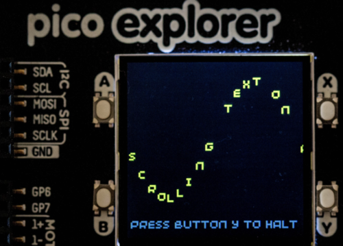
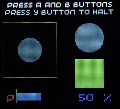
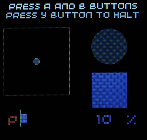
It illustrates the character set, drawing of lines, circles and boxes; plotting graphs, writing text at an angle or following a curved path, scrolling text along a sine curve, controlling an interactive bar graph with the buttons, updating a numeric value, changing the size and brightness of disks, and the colour of a rectangle.
The program is fully commented, so it should be quite easy to follow.
The most common coding mistake is to forget the display.update() instruction after drawing something. The second is putting it in the wrong place.
When overwriting text on the screen to update a changing value, you should first overwrite the value with a small rectangle in the background colour. Notice that the percentage value is right-aligned to lock the ‘units’ position.
It’s probably not a good idea to leave your display brightly lit for hours at a time. Several people have reported the appearance of ‘burn’ on a dark background, or ‘ghost’ marks after very bright items against a dark background have been displayed for some time. We’ve seen them on our display, but no long-term harm is evident. Blanking the screen in the ‘tidy-up’ sequence at the end of your program may help.
We hope you have found this tutorial useful and that it encourages you to start sending your output to a display. This is so much more rewarding than just printing to the REPL.
If you have a Pimoroni Pico Display, (240×135 pixels), all of these routines will work on your board.
Issue 41 of HackSpace magazine is on sale NOW!
Each month, HackSpace magazine brings you the best projects, tips, tricks and tutorials from the makersphere. You can get it from the Raspberry Pi Press online store or your local newsagents. As always, every issue is free to download from the HackSpace magazine website.
You can always rely on Ryder’s YouTube channel to be full of weird and wonderful makes. This latest offering aims to boost dopamine levels with dog spotting. Looking at dogs makes you happier, right? But you can’t spend all day looking out of the window waiting for a dog to pass, right? Well, a Raspberry Pi Camera Module and machine learning can do the dog spotting for you.
What’s the setup?
Ryder’s Raspberry Pi and camera sit on a tripod pointing out of a window looking over a street. Live video of the street is taken by the camera and fed through a machine learning model. Ryder chose the YOLO v3 object detection model, which can already recognise around 80 different things — from dogs to humans, and even umbrellas.
Camera set up ready for dog spotting
Doggo passing announcements
But how would Ryder know that his Raspberry Pi had detected a dog? They’re so sneaky — they work in silence. A megaphone and some text-to-speech software make sure that Ryder is alerted in time to run to the window and see the passing dog. The megaphone announces: “Attention! There is a cute dog outside.”
The machine learning program clearly labels a ‘person’ and a ‘dog’
“Hey! Cute dog!”
Ryder wanted to share the love and show his appreciation to the owners of cute dogs, so he added a feature for when he is out of the house. With the megaphone poking out of a window, the Raspberry Pi does its dog-detecting as usual, but instead of alerting Ryder, it announces: “I like your dog” when a canine is walked past.
When has a megaphone ever NOT made a project better?
Also, we’d like to learn more about this ‘Heather’ who apparently once scaled a six-foot fence to pet a dog and for whom Ryder built this. Ryder, spill the story in the comments!
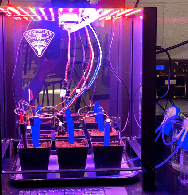
In the latest issue of The MagPi Magazine, out today, Rob Zwetsloot talks to teacher Chris Regini about the incredible project his students are working on.
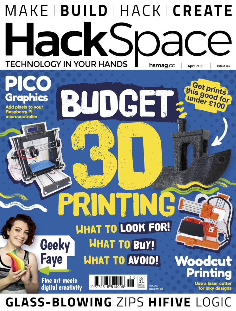
When we think of garden automation, we often think of basic measures like checking soil moisture and temperature. The Kay-Berlin Food Computer, named after student creators Noah Kay and Noah Berlin, does a lot more than that. A lot more.
At night, an IR LED floodlight allows for infrared camera monitoring via a Raspberry Pi NoIR Camera Module
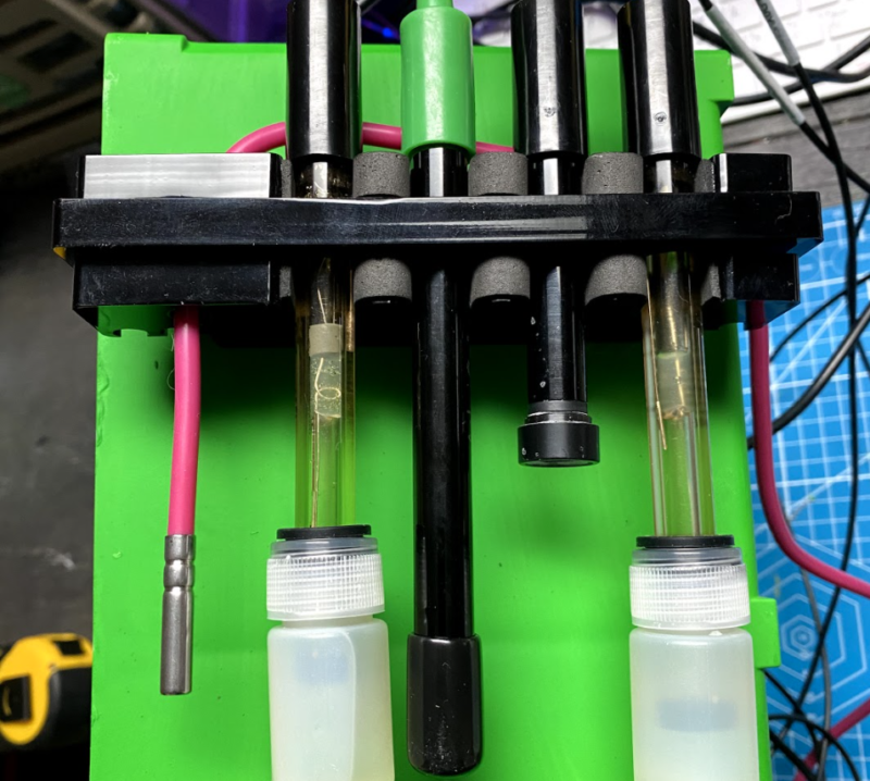
“It is a fully automated growth chamber that can monitor over a dozen atmospheric and root zone variables and post them to an online dashboard for remote viewing,” Chris Regini tells us. He’s supervising both Noahs in this project. “In addition to collecting data, it is capable of adjusting fan speeds based on air temperature and humidity, dosing hydroponic reservoirs with pH adjustment and nutrient solutions via peristaltic pumps, dosing soil with water based on moisture sensor readings, adjusting light spectra and photoperiods, and capturing real-time and time-lapsed footage using a [Raspberry Pi] Camera Module NoIR in both daylight and night-time growth periods.”
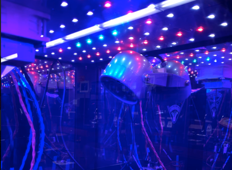
Everything can be controlled manually or set to be autonomous. This isn’t just keeping your garden looking nice, this is the future of automated farming.
All the data is used for automation, but it’s accessible to students for manual control
Seeds of knowledge
“The idea originated from the long standing MIT food computer project and lots of open-source collaboration in both the agriculture and Raspberry Pi communities,” Chris explains. “We’ve always had the hopes of creating an automated growing system that could collect long-term data for use in the ISS during space travel or in terrestrial applications where urbanisation or climate concerns required the growth of food indoors.”
With students doing a lot of learning from home in the past year, having such a system accessible online for interaction was important for Chris: “Adding a layer that could keep students engaged in this endeavour during remote learning was the catalyst that truly spurred on our progress.”
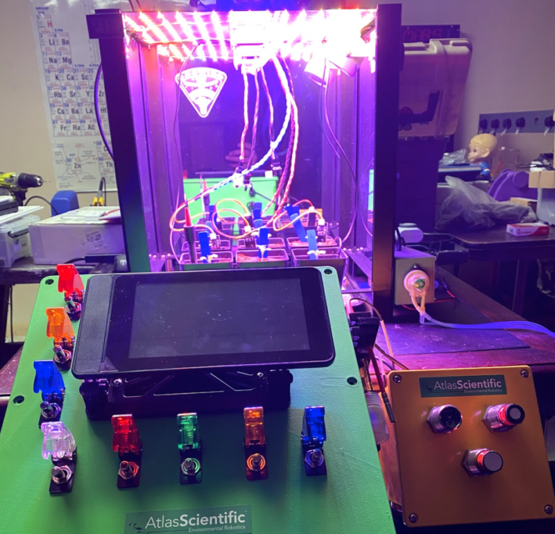
“All data is viewable in real time and historically,
This level of control and web accessibility is perfect for Raspberry Pi, which Chris, his students, and his Code Club have been using for years.
“The fact that we had access to the GPIOs for sensors and actuators as well as the ability to capture photo and video was great for our application,” Chris says. “Being able to serve the collected data and images to the web, as well as schedule subroutines via systemd, made it the perfect fit for accessing our project remotely and having it run time-sensitive programs.”
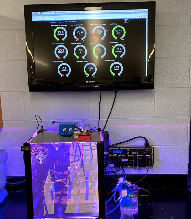
There are six plants in the box, allowing for a lot of data collection
The computer has been in development for a while, but the students working on it have a wide range of skills that have made it possible.
“We have had a dedicated nucleus of students that have spent time learning plant science, electronic circuitry, Python, developing UIs, and creating housings in CAD,” Chris explains. “They all started as complete beginners and have benefited greatly from the amazing tutorials available to them through the Raspberry Pi Foundation website as well as the courses offered on FutureLearn.”
Grow beyond
The entire system has a network of sensors which monitor atmospheric variables of air temperature, humidity, CO2, O2, and air pressure.
The project is ongoing – although they’re already getting a lot of data that is being used for citizen science.
“The system does a fantastic job collecting data and allowing us to visualise it via our Adafruit IO+ dashboards,” Chris says. “Upgrading our sensors and actuators to more reliable and accurate models has allowed the system to produce research level data that we are currently sharing in a citizen science project called Growing Beyond Earth. It is funded by NASA and is organised through Fairchild Botanical Gardens. We have been guided along the way by industry professionals in the field of hydroponics and have also collaborated with St. Louis-based MARSfarm to upgrade the chamber housing, reflective acrylic panels, and adjustable RGBW LED panel. Linking our project with scientists, engineers, researchers, and entrepreneurs has allowed it to really take off.”
Get your copy of The Magpi #104 now!
You can grab the brand-new issue right now online from the Raspberry Pi Press store, or via our app on Android or iOS. You can also pick it up from supermarkets and newsagents, but make sure you do so safely while following all your local guidelines. There’s also a free PDF you can download.
Raspberry Pi Pico has a lot of interesting and unique features, but it doesn’t have networking. Of course this was only ever going to be a temporary inconvenience, and sure enough, over Pi Day weekend we saw both USB Ethernet and Ethernet PHY support released for Pico and RP2040.
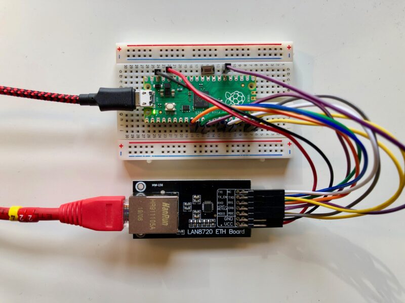
Raspberry Pi Pico and RMII Ethernet PHY
The PHY support was put together by Sandeep Mistry, well known as the author of the noble and bleno Node.js libraries, as well as the Arduino LoRa library, amongst others. Built around the lwIP stack, it leverages the PIO, DMA, and dual-core capabilities of RP2040 to create an Ethernet MAC stack in software. The project currently supports RMII-based Ethernet PHY modules like the Microchip LAN8720.
Breakout boards for the LAN8720 can be found on AliExpress for around $1.50. If you want to pick one up next day on Amazon you should be prepared to pay somewhat more, especially if you want Amazon Prime delivery, although they can still be found fairly cheaply if you’re prepared to wait a while.
What this means is that you can now connect your $4 microcontroller to an Ethernet breakout costing less than $2 and connect it to the internet.
Building from source
If you don’t already have the Raspberry Pi Pico toolchain set up and working, you should first set up the C/C++ SDK. Afterwards you need grab the the project from GitHub, along with the lwIP stack.
Make sure you have your PICO_SDK_PATH set before before proceeding. For instance, if you’re building things on a Raspberry Pi and you’ve run the pico_setup.sh script, or followed the instructions in our Getting Started guide, you’d point the PICO_SDK_PATH to
If everything goes well you should have a UF2 file in build/examples/httpd called pico_rmii_ethernet_httpd.uf2. You can now load this UF2 file onto your Pico in the normal way.
Go grab your Raspberry Pi Pico board and a micro USB cable. Plug the cable into your Raspberry Pi or laptop, then press and hold the BOOTSEL button on your Pico while you plug the other end of the micro USB cable into the board. Then release the button after the board is plugged in.
A disk volume called RPI-RP2 should pop up on your desktop. Double-click to open it, and then drag and drop the UF2 file into it. Your Pico is now running a webserver. Unfortunately it’s not going to be much use until we wire it up to our Ethernet breakout board.
Wiring things up on the breadboard
Unfortunately the most common (and cheapest) breakout for the LAN8720 isn’t breadboard-friendly, although you can find some boards that are, so you’ll probably need to grab a bunch of male-to-female jumper wires along with your breadboard.
LAN8720 breakout wired to a Raspberry Pi Pico on a breadboard (with reset button)
Then wire up the breakout board to your Raspberry Pi Pico. Most of these boards seem to be well labelled, with the left-hand labels corresponding to the top row of breakout pins. The mapping between the pins on the RMII-based LAN8720 breakout board and your Pico should be as follows:
Pico
RP20401
LAN8720 Breakout
Pin 9
GP6
RX0
Pin 10
GP7
RX1 (RX0 + 1 )
Pin 11
GP8
CRS (RX0 + 2)
Pin 14
GP10
TX0
Pin 15
GP11
TX1 (TX0 + 1)
Pin 16
GP12
TX-EN (TX0 + 2)
Pin 19
GP14
MDIO
Pin 20
GP15
MDC
Pin 26
GP20
nINT / RETCLK
3V3 (OUT)
—
VCC
Pin 38
GND
GND
Mapping between physical pin number, RP2040 pin, and LAN8720 breakout
1 These pins are the library default and can be changed in software.
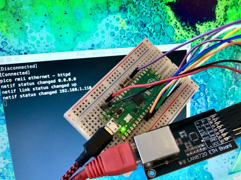
Once you’ve wired things up, plug your Pico into Ethernet and also via USB into your Raspberry Pi or laptop. As well as powering your Pico you’ll be able to see some debugging information via USB Serial. Open a Terminal window and start minicom.
If you’re having problems, see Chapter 4 of our Getting Started guide for more information.
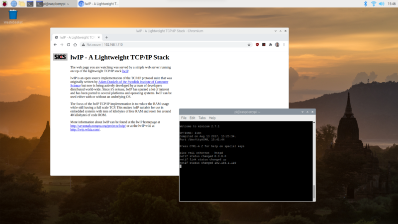
Hopefully, so long as your router is handing out IP addresses, you should see something like this in the minicom window, showing that your Pico has grabbed an IP address using DHCP:
If you open up a browser window and type the IP address that your router has assigned to your Pico into the address bar, if everything goes well you should see the default lwIP index page:
Viewing the web page served from our Raspberry Pi Pico.
Congratulations. Your Pico is now a web server.
Changing the web pages
It turns out to be pretty easy to change the web pages served by Pico. You can find the “file system” with the default lwIP pages inside the HTTP application in the lwIP Git submodule.
You should modify the index.html file in situ here with your favourite editor. Afterwards we’ll need to move the file system directory into place, and then we can repackage it up using the associated makefsdata script.
Running this script will create an fsdata.c file in the current directory. You need to move this file up to the parent directory and then rebuild the UF2 file.
If everything goes well you should have a new UF2 file in build/examples/httpd called pico_rmii_ethernet_httpd.uf2 , and you can again load this UF2 file onto your Pico as before.
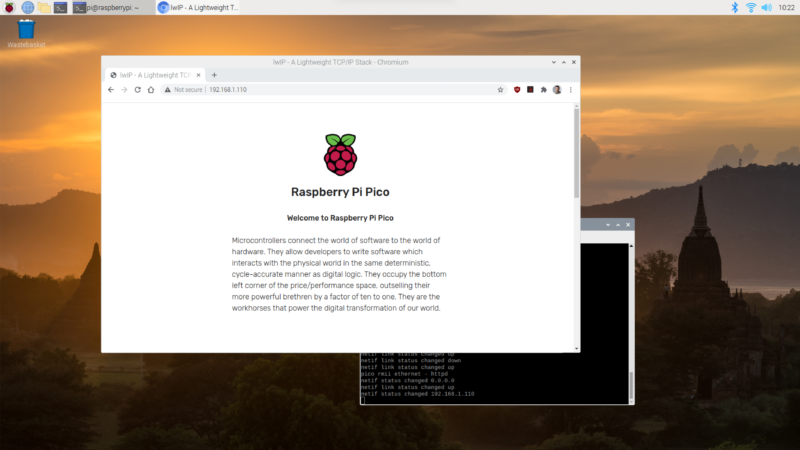
The updated web page served from our Raspberry Pi Pico
On restart, wait till your Pico grabs an IP address again and then, opening up a browser window again and typing the IP address assigned to your Pico into the address bar, you should now see an updated web page.
You can go back and edit the page served from your Pico, and build an entire site. Remember that you’ll need to rebuild the fsdata.c file each time before your rebuild your UF2.
Current limitations
There are a couple of limitations on the current implementation. The RP2040 is running underclocked to just 50MHz using the RMII modules’ reference clock, while the lwIP stack is compiled with NO_SYS so neither the Netcon API nor the Socket API is enabled. Finally, link speed is set to 10 Mbps as there is currently an issue with TX at 100 Mbps.
Where next?
While the example Sandeep put together used the lwIP web server, there are a number of other library application examples we can grab and twist to our own ends, including TFTP and MQTT example applications. Beyond that, lwIP is a TCP/IP stack. Anything you can do over TCP you can now do from your Pico.
Wrapping up
Support for developing for Pico can be found on the Raspberry Pi forums. There is also an (unofficial) Discord server where a lot of people active in the new community seem to be hanging out. Feedback on the documentation should be posted as an Issue to the pico-feedback repository on GitHub, or directly to the relevant repository it concerns.
All of the documentation, along with lots of other help and links, can be found on the Getting Started page. If you lose track of where that is in the future, you can always find it from your Pico: to access the page, just press and hold the BOOTSEL button on your Pico, plug it into your laptop or Raspberry Pi, then release the button. Go ahead and open the RPI-RP2 volume, and then click on the INDEX.HTM file.
This automated analogue film scanner runs on a Raspberry Pi and LEGO bricks. BenjBez took to Reddit to share this incredible lockdown project, which makes processing film photographs easier.
“When doing analog photography, scanning is the most painful part – RoboScan tries to make the whole workflow easier, from the film to the final image file.”
Mesmerising, isn’t it? We don’t know why we want it, we just do. We love it when new technology supports traditional methods with hacks like this. It reminded us of this Raspberry Pi powered e-paper display that takes months to show a movie.
How does it work?
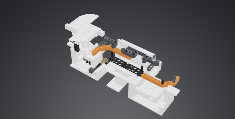
A 3D rendering of the LEGO parts used to make the scanner, from Mecabricks
The film roll is fed through the LEGO frame and lit by an integrated LED backlight. Machine learning detects when a photo is correctly framed and ready for scanning, then a digital camera takes another photo of it. RoboScan downloads the photos from your digital camera as soon as they are taken. Only 80 photos were used to train the Raspberry Pi and Benj has shared the model here.
This is what the machine learning sees. In purple are the tentative complete frames
But I only take digital photos anyway…
Most of us rely on our phones these days to capture special moments. However, we bet loads of you have relatives with albums full of precious photos they would hate to lose; maybe you could digitise the negatives for safekeeping using this method?
Benj is still working on his creation, sharing this updated version a few months ago
Best of all – it’s all open source and available on GitHub.
Thanks, Electromaker!
Skip to 16 mins 37 seconds to watch electromaker’s take on this project
We love our lovely friends at Electromaker and we found this project through them. (They found it on Reddit.) They release a new video every week, so make sure to subscribe on YouTube so you don’t miss out.
We are delighted to announce that we’re expanding our free Isaac Computer Science online learning platform in response to overwhelming demand from teachers and students for us to cover GCSE content.
Thanks to our contract with England’s Department for Education which is funding our work as part of the National Centre for Computing Education (NCCE) consortium, we’ve been able to collaborate with the University of Cambridge to build the Isaac Computer Science platform, and to create an events programme, for A level students and teachers. Now we will use this existing funding to also provide content and events for learning and teaching GCSE computer science.
Building on our success
With content designed by our expert team of computer science teachers and researchers, the Isaac Computer Science platform is already being used by 2000 teachers and 18,000 students at A level. The platform houses a rich set of interactive study materials and reflective questions, providing full coverage of exam specifications.
Within the Teach Computing Curriculum we built as part of our NCCE work, we’ve already created free classroom resources to support teachers with the delivery of GCSE computer science (as well as the rest of the English computing curriculum from Key Stages 1 to 4). Expanding the Isaac Computer Science platform to offer interactive learning content to GCSE students, and running events specifically for GCSE students, will perfectly complement the Teach Computing Curriculum and support learners to continue their computing education beyond GCSE.
We’ll use our tried and tested process of content design, implementation of student and teacher feedback, and continual improvements based on evidence from platform usage data, to produce an educational offering for GCSE computer science that is of the highest quality.
What will Isaac Computer Science GCSE cover?
Isaac Computer Science GCSE will support students and teachers of GCSE computer science across the OCR, AQA, Eduqas and WJEC exam bodies, covering the whole of the national curriculum. The content will be aimed at ages 14 to 16, and it will be suitable for students of all experience levels and backgrounds — from those who have studied little computer science at Key Stage 3 and are simply interested, to those who are already set to pursue a career related to computer science.
Benefits for students and teachers
Students will be able to:
Use the platform for structured, self-paced study and progress tracking
Prepare for their GCSE examinations according to their exam body
Get instant feedback from the interactive questions to guide further study
Explore areas of interest more deeply
Teachers will be able to:
Use the content and examples on the platform as the basis for classroom work
Direct their students to topics to read as homework
Set self-marking questions as homework or in the classroom as formative assessment to identify areas where additional support is required and track students’ progress
Free events for learning, training, and inspiration
As part of Isaac Computer Science GCSE, we’ll also organise an events programme for GCSE students to get support with specific topics, as well as inspiration about opportunities to continue their computer science education beyond GCSE into A level and higher education or employment.
For teachers, we’ll continue to provide a wide spectrum of free CPD training events and courses through the National Centre for Computing Education.
Accessible all over the world
As is the case for the Isaac Computer Science A level content, we’ll create content for this project to suit the English national curriculum and exam bodies. However, anyone anywhere in the world will be able to access and use the platform for free. The content will be published under an Open Government License v3.0.
When does Isaac Computer Science GCSE launch, and can I get involved now?
Our launch will be in January of 2022, with the full suite of content available by September of 2022.
We’ll be putting out calls to the teaching community in England, asking for your help to guide the design and quality assurance of the Isaac Computer Science GCSE materials.
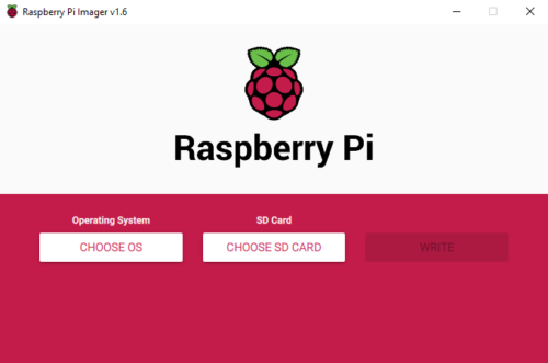
Since Raspberry Pi Imager was released just over a year ago, we’ve made a number of changes and fixes to help make it more reliable and easier to use.
But you may wonder whether it’s changed at all, because it looks almost exactly the same as it did last year. That’s not a coincidence — we’ve deliberately kept it as simple and straightforward as we can.
Raspberry Pi Imager
Our mission in designing and developing Imager was to make it as easy to use as possible, with the smallest possible number of clicks. This reduces complexity for the user and reduces the scope for users to make mistakes. However, at the same time, some of our users were asking for more complex functionality. This presented me with a tricky problem: how could we support advanced functionality, while also making it easy to use and hard to get wrong?
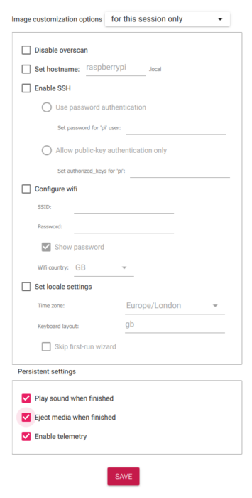
After much wrangling in GitHub issues, I finally folded, and decided to introduce an advanced options menu.
For those you adventurous enough to want to play with the advanced options, you need to press the magic key sequence:
‘Ctrl-Shift-X’
Using the advanced options menu obviously involves a few extra clicks, but it’s actually pretty simple, and it’s worth a look if you find you frequently need to make config changes after you flash a new SD card. It allows you to set some common options (for example, if you set the hostname correctly you don’t need to have a static IP address), and you can either save these for future images or use them for this session only.
If you’d like to turn off telemetry, that’s fine; all it does is send a ping to the Raspberry Pi website that lets us create the statistics pages here. To understand what we send, you can read about it on our GitHub page.
Try Raspberry Pi Imager today
Raspberry Pi Imager is available for Windows, macOS, Ubuntu for x86, and Raspberry Pi OS. Download options are available on our Downloads page, or you can use sudo apt install rpi-imager in a Terminal window to install it on a Raspberry Pi.
Once installed, simply follow the on-screen instructions and you’re good to go. Here’s a handy video to show just how easy it is to prepare your SD card.
Although it’s a very flexible term, supercomputing generally refers to the idea of running multiple computers as one, dividing up the work between them so that they process in parallel.
In theory, every time you double the amount of processing power available, you half the time needed to complete your task. This concept of ‘clusters’ of computers has been implemented heavily in large data processing operations, including intensive graphics work such as Pixar’s famous ‘render farm’. Normally the domain of large organisations, supercomputing is now in the hands of the masses in the form of education projects and makes from the cluster-curious, but there have also been some impressive real-world applications. Here, we’ll look at some amazing projects and get you started on your own supercomputing adventure.
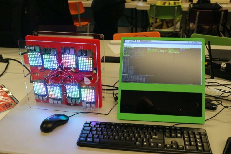
OctaPi
One of the first high-profile cluster projects surprisingly came from the boffins at GCHQ (Government Communications Headquarters) in the UK. Created as part of their educational outreach programme, the OctaPi used eight Raspberry Pi 3B computers to create a cluster. Kits were loaned out to schools with multiple coding projects to engage young minds. The first demonstrated how supercomputing could speed up difficult equations by calculating pi. A more advanced, and very appropriate, task showed how these eight machines could work together to crack a wartime Enigma code in a fraction of the time it would have taken Bletchley Park.
Turing Pi
As we’ve already said, most Raspberry Pi cluster projects are for education or fun, but there are those who take it seriously. The Raspberry Pi Compute Module form factor is perfect for building industrial-grade supercomputers, and that’s exactly what Turing Pi has done. Their custom Turing Pi 1 PCB can accept up to seven Raspberry Pi 3+ Compute Modules and takes care of networking, power, and USB connectivity. Although claiming a wide range of uses, it appears to have found a niche in the Kubernetes world, being a surprisingly powerful device for its price. Future plans have been announced for the Turing Pi 2, based on the more powerful Raspberry Pi 4.
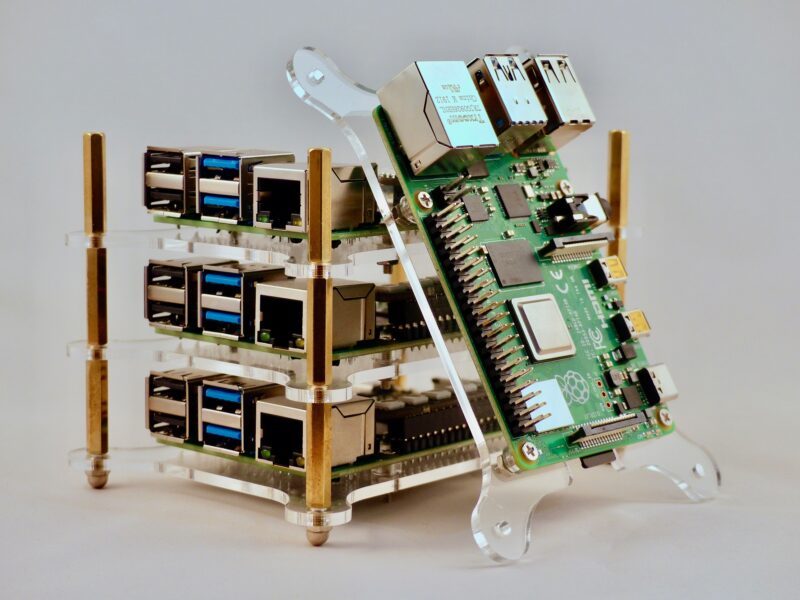
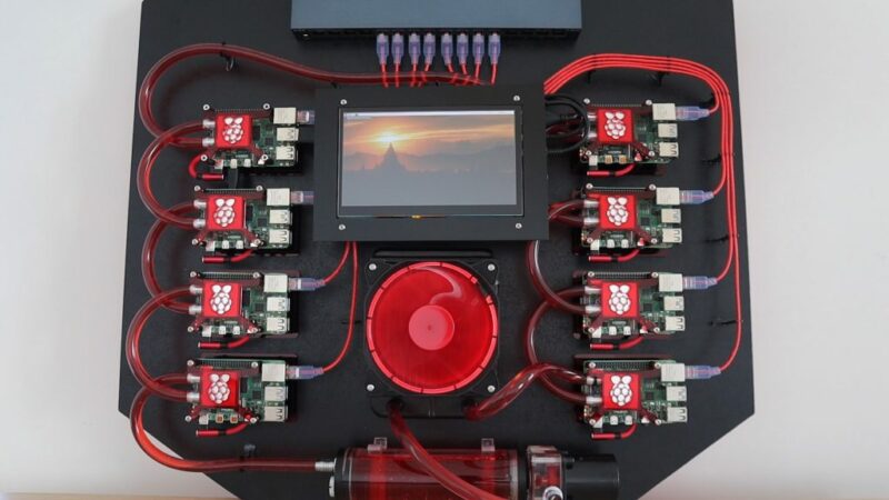
Water-Cooled Cluster
Multiple machines are one thing, but there’s also the individual speed of those machines. The faster they go, the faster the cluster operates exponentially. Overclocking is common in supercomputing, and that means heat. This water-cooled cluster, which maker Michael Klements freely admits is one of those ‘just because’ undertakings, uses the kind of water cooling usually found on high-end gaming PCs and applies it to a Raspberry Pi cluster. This beautiful build, complete with laser-cut mounts and elegant wiring, has been extensively documented by Klements in his blog posts. We can’t wait to see what he does with it!
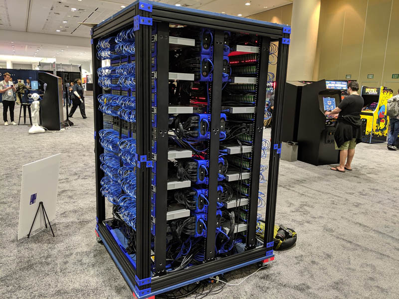
Oracle Supercomputer
So how far can we take this? Who has built the largest Raspberry Pi cluster? A strong contender seems to be Oracle, who showed off their efforts at Oracle OpenWorld in 2019. No fewer than 1060 Raspberry Pi 3B+ computers were used in its construction (that’s 4240 cores). Why 1060? That’s as much as they could physically fit in the frame! The creation has no particular purpose bar a demonstration of what is possible in a small space, cramming in several network switches, arrays of USB power supplies, and a NAS (network-attached storage) for boot images.
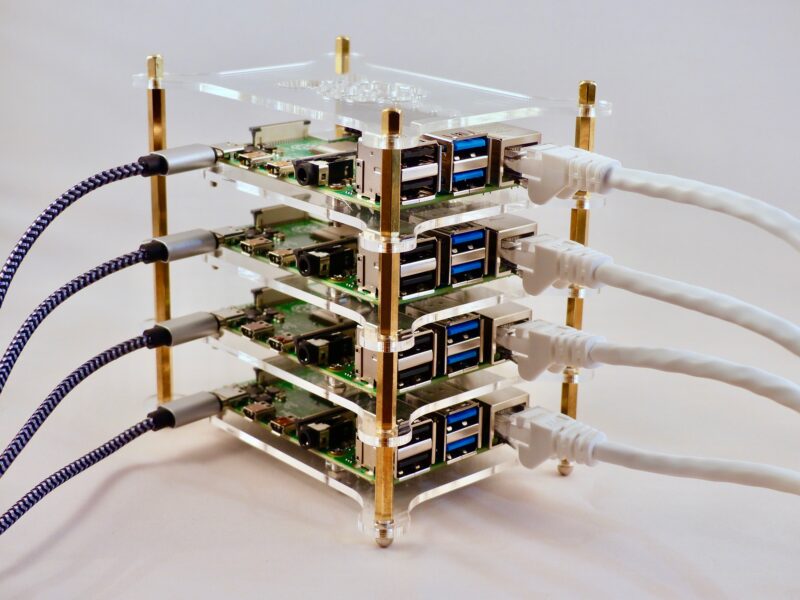
Make your own
We’re thinking you probably don’t fancy trying to beat Oracle’s record on your first attempt, and would like to start with something a bit simpler. Our sister magazine, The MagPi, has published a cluster project you can make at home with any number of Raspberry Pi devices (although just one might be a little pointless). In this case, four Raspberry Pi 4B computers were assigned the job of searching for prime numbers. Each is assigned a different starting number, and then each adds four before testing again. This is handled by an open-source cluster manager, MPI (Message Passing Interface). A solid introduction to what is possible.
Issue 41 of HackSpace magazine is on sale NOW!
Each month, HackSpace magazine brings you the best projects, tips, tricks and tutorials from the makersphere. You can get it from the Raspberry Pi Press online store or your local newsagents. As always, every issue is free to download from the HackSpace magazine website.
Picture the scene – you’ve just returned from an amazing trip armed with hundreds of photos. You don’t want to lose those memories. However, you also don’t want to spend the next three hours uploading and organising them.
An automated solution
Lou Kratz spends pretty much every weekend capturing his adventures on camera. But he couldn’t stand the digital admin, so he invented PiPhoto to automate the process.
As you can see from the video, Lou has created a wonderfully simple solution. You just plug your SD card into your Raspberry Pi, and your photos automatically upload onto your computer. Game changer.
What does PiPhoto do?
Mount the SD card on insert
Start flashing the green LED
Execute a sync command of your choosing
Make the green LED solid when the command completes
Make the red LED flash if the sync command fails
Can I build one myself?
Yes! Lou is our most favourite kind of maker in that he has open-sourced everything on GitHub. There are also step-by-step instructions on Lou’s blog.
PiPhoto cycling through on Raspberry Pi
You can easily change the sync command to better fit your needs, and Lou has already made some improvements. Here is a guide to making your Raspberry Pi organise photos by date as they’re uploaded. You can keep up with any new additions via Lou’s GitHub.
Now we don’t have to ditch our beloved older cameras for newer models with wireless connectivity built in. Thanks Lou!
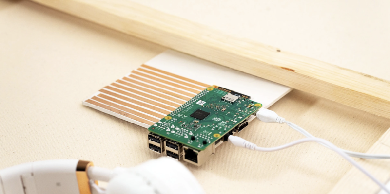
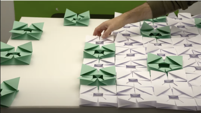
Ross Symons is an incredible origami artist who harnessed Raspberry Pi and Bare Conductive’s Pi Cap board to bring his traditional paper creations to life in an interactive installation piece.
The Pi Cap is “[a]n easy-to-attach add-on board that brings capacitive sensing to your Raspberry Pi projects.” Capacitive sensing is how touchscreens on your phone and tablet work: basically, the Pi Cap lets the Raspberry Pi know when something – in this case, an origami flower – is being touched.
Ross named his creation “Wonder Wall – an Origami Meditation Mural”. Visitors put on headphones next to the origami flower wall, and listen to different soothing sounds as the Pi Cap senses that one of the green flowers is being touched.
The Raspberry Pi runs code from Python library PyGame to achieve the sound effects.
Origami flowers ready for the installation. Photo from Bare Conductive
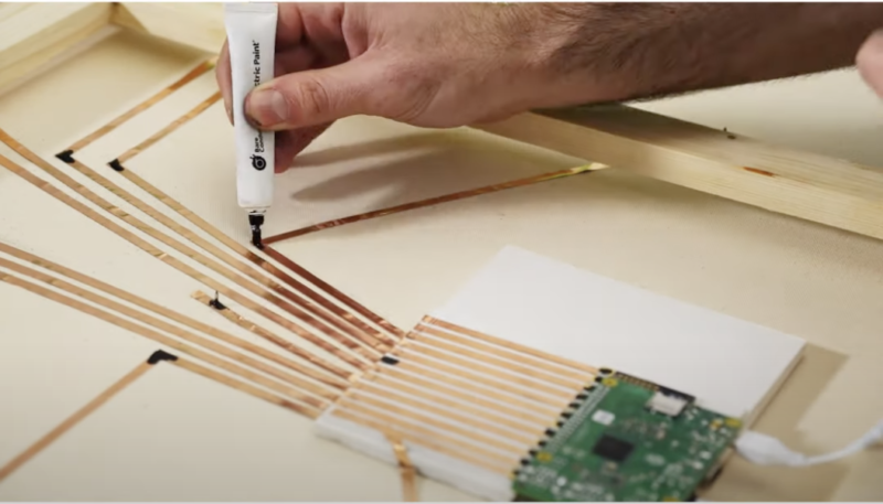
Electric paint
64 origami flowers were mounted to a canvas, a much lighter and more readiliy transportable option than a big wooden board.
On the back of the board, the Pi Cap and Raspberry Pi connect to each origami flower with electric paint and copper tape. The electric paint “solders” the copper tape to the Pi Cap, and also allows for connections around corners.
Drop a comment below if you’ve ever used electric paint in a project.
The Pi Cap board connects to origami flowers with electric paint (being applied from the white tube) and copper tape. Photo from Bare Conductive
Insta-cutie
Check out Ross’s beautiful Instagram account @white_onrice. It’s full of incredible paper creations and inspired stop-motion animations. Our favourite is this little crane having a whale of a time.
Updating a 22-year-old game brought Andrew Gillett face to face with some very poor coding practices. Read more about it in this brilliant guest article from the latest issue of Wireframe magazine.
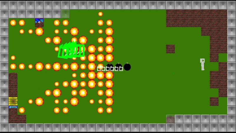
In 1998, at the age of 17, I was learning how to write games in C. My first attempt, the subtly titled DEATH, was not going well. The game was my take on Hardcore, a 1992 Atari ST game by legendary game developer and sheep enthusiast Jeff Minter, which had been released only as an unfinished five-level demo.
A series of ultrabombs blowing up a snake.
The player controlled four gun turrets on the outside of a square arena, into which enemies teleported. While the original game had been enjoyable and promising, my version wasn’t much fun, and I couldn’t work out why. Making a decent game would also have involved making dozens of levels and many enemy types, which was looking like too big a task, especially as I was finding it hard to understand the intricacies of how the enemies in Hardcore moved.
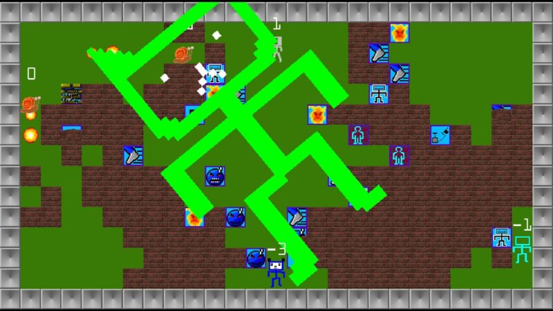
So I abandoned that game and decided to replicate a different one – 1994’s MasterBlaster, a Bomberman-style game on the Commodore Amiga. MasterBlaster didn’t have a single-player mode or bots, so there was no enemy AI to write. And the level was just a grid with randomly generated walls and power-ups – so there was no real level design involved. With those two hurdles removed, development went fairly smoothly, the biggest challenge being working out some of the subtleties of how character movement worked.
The 2021 version of Partition Sector
The game, which I named Partition Sector, was finished in mid-1999 and spent the next 18 years on my website being downloaded by very few people. In late 2018 I decided to do a quick update to the game and release it on Steam. Then I started having ideas, and ended up working on it, on and off, for two years.
One of the biggest hurdles I came across when writing my first games was how to structure the code. I knew how to write a basic game loop, in which you update the positions of objects within the game, then draw the level and the objects within it, and then loop back to the start, ending the loop when the ‘game over’ criteria are met or the player has chosen to quit. But for a full game you need things like a main menu, submenus, going through a particular number of rounds before returning to the main menu, and so on. In the end, I was able to come up with something that worked, but looking back on my old code 20 years on, I could see many cases of absolutely terrible practice.
“I started having ideas, and ended up working on it, on
and off, for two years”
While most of my time was spent adding new features, a lot of time was spent rewriting and restructuring old code. I’m going to share some examples from the original code so you don’t make the same mistakes!
This is just a snippet of Andrew’s brilliant monster-sized tutorial, which you can read in full in the latest issue of Wireframe magazine. No subscription? No problem! You can read the rest of this post in full for free in PDF format.
You can read more features like this one in Wireframe issue 48, available directly from Raspberry Pi Press — we deliver worldwide.
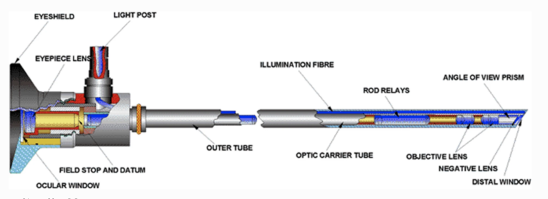
Researchers at the University of Cape Town set about developing an affordable wireless endoscope camera to rival expensive, less agile options.
Endoscopic cameras are used to look at organs inside your body. A long, thin, flexible tube with a light at the end is fed down your throat (for example), and an inside view of all your organs is transmitted to a screen for medical review.
Problem is, these things are expensive to build. Also, the operator is tethered by camera wires and power cables.
The prototype featured in Lazarus & Ncube research paper
With this low-cost prototype, the camera is mounted at the end with LEDs instead of fibre-optic lights. The device is battery powered, and can perform for two hours without needing a charge. Traditional endoscopes require external camera cables and a hefty monitor, so this wireless option saves space and provides much more freedom. Weighing in at just 184g, it’s also much more portable.
The prototype incorporates a 1280 × 720 pixel high-definition tube camera, and transmits video to a standard laptop for display. Perhaps this idea could be developed to support an even more agile display, such as a phone or a touchscreen tablet.
Thousands of dollars cheaper
This Raspberry Pi-powered wireless option also saves thousands of dollars. It was built for just $230, whereas contemporary wired options cost around $28,000.
Urologists at the University of Cape Town created the prototype. J. M. Lazarus & M. Ncube hope their design will be more accessible to medical settings that have less money available. You can read their research paper for an in-depth look at the whole process.
A traditional endoscope. Image from Lazarus & Ncube’s original paper
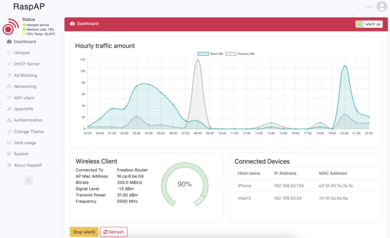
The researchers focused on open-source resources to keep the cost low; we’ll learn more about the RaspAP software they used below. Affordability also led them to Raspberry Pi Zero W which, at just $10, is able to handle high-definition video.
What is RaspAP?
Billz, who shared the project on reddit, is one of the developers of RaspAP.
RaspAP is a wireless setup and management system that lets you get a wireless access point up and running quickly on Raspberry Pi. Here, the Raspberry Pi is receiving images sent from the camera and transmitting them to a display device.
An example of a RaspAP dashboard
There is also Quick installer available for RaspAP. It creates a default configuration that “just works” on all Raspberry Pis with onboard wireless.
We wonder what other medical equipment could be greatly improved by developing an affordable wireless version?
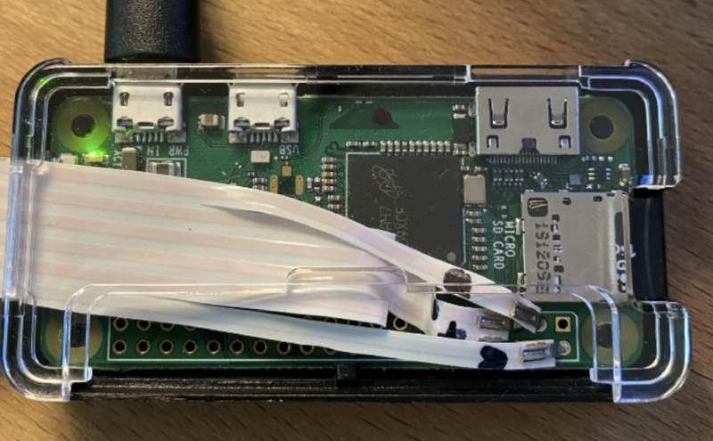
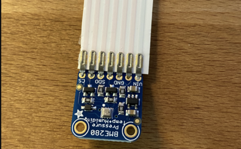
Elizabeth from Git Tech’d has shown us how to monitor freezers and fridges remotely with a temperature sensor and Raspberry Pi. A real-time temperature monitor dashboard lets you keep an eye on things, and text message alerts can be set up to let you know when the temperature is rising.
The idea came about after Rick Kuhlman‘s wife lost a load of breast milk she had stored in the freezer. To make sure that months of hard work was never wasted again, Rick came up with this $30 solution.
Flat Flex cable — only the flattest cables can bridge the seal of a freezer without causing an air leak
Everything packed together in the protective case
Setup
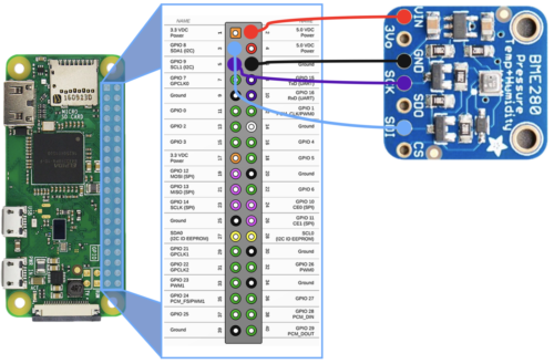
Easy does it: you just wire the temperature sensor directly to your Raspberry Pi. Rick has even made you a nice wiring diagram, so no excuses:
There’s a little fiddling to make sure your Flat Flex cable attaches properly to the temperature sensor. The project walkthrough provides a really clear, illustrated step-by-step to help you.
The temperature sensor has seven solder points but the cable has eight connectors, so you’ll need to get snippy
Software
Everything looks pretty simple according to the installation walkthrough. A couple of Python libraries accessed via Raspberry Pi OS and you’re there.
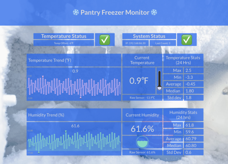
Initial State’s temperature monitor dashboard
You’ll need an access key from Initial State, but Rick explains you can get a free trial. The real-time temperature monitor dashboard is hosted on your Initial State account. If you want to have a poke around one that’s already up and running, have a look at Rick’s dashboard.
Alert!
You can configure your own alert parameters from within the dashboard. Set your desired temperature and how much leeway you can tolerate.
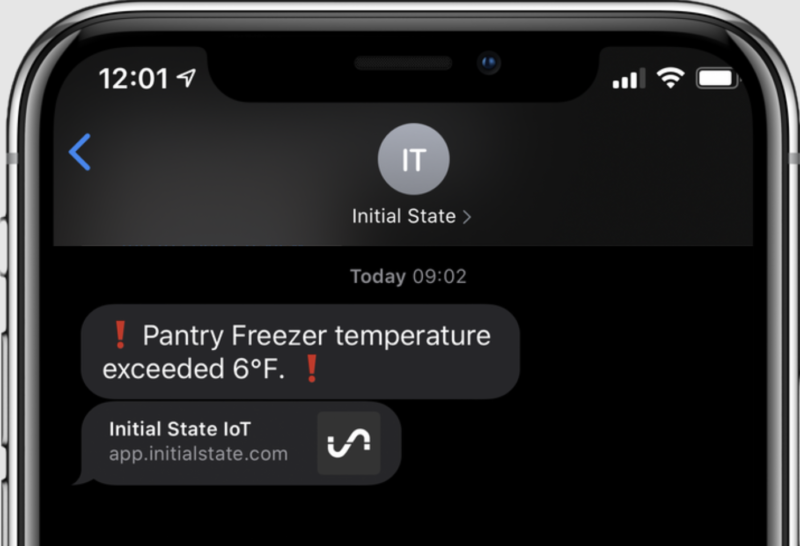
You’ll get a text alert if the temperature falls too far above or below your personal setting.
Get alerts straight to your phone
We can see this affordable fix helping out science labs that need to keep their expensive reagents cold but don’t have the budget for freezers with built-in monitoring, as well as people who need to keep medication at a certain temperature at home. Or maybe food outlets that don’t want to risk losing loads of pricy perishables stacked up in a chest freezer. Nice work, Rick and Elizabeth!
Since launching our first-ever Pi Day fundraising campaign, we’ve been absolutely amazed by the generous support so many of you have shown for the young learners and creators in our community. Together, our Pi Day donors have stepped up to make an impact on over 20,000 learners (and counting!) who rely on the Raspberry Pi Foundation’s free digital making projects and online learning resources.
We need your help to keep the momentum going until 14 March, so that as many young people as possible gain the opportunity to develop new skills and get creative with computing. If you are able to contribute, there’s still time for you to join in with a gift of £3.14, £31.42, or perhaps even more.
We can’t thank you enough for your support, and as a way to show our gratitude, we offer you the option to see your name listed as a Pi Day donor in an upcoming issue of The MagPi magazine!
Join our live online Pi Day celebration
We’d also like to invite you to our virtual Pi Day celebration! This Sunday at 7pm GMT, we’ll host a special episode of Digital Making at Home, our weekly live stream for families and young digital makers. Eben will be on to share the story of Raspberry Pi, and of course we’ll be making something cool with Raspberry Pi and celebrating with all of you. Subscribe to the Foundation’s YouTube channel and turn on notifications to get a reminder about when we go live.
A little help from our friends
Last but not least, we’d like to extend a big thank you to OKdo. They’re celebrating Pi Day with special deals throughout the weekend, and a generous 50% of those proceeds will be donated to the Raspberry Pi Foundation.
“We’re delighted to be supporting Raspberry Pi’s first ever Pi Day Campaign. Events like this are vital to aid our mutual mission to make technology accessible to young people all over the world. At OKdo we exist to spark a love of computing for children and help them to develop new skills so that they have every possible chance to fulfil their potential.”
Richard Curtin, OKdo’s SVP
We’re grateful to OKdo for championing our Pi Day campaign along with our friends at EPAM Systems and CanaKit.
Happy Pi Day, and we can’t wait to celebrate with you this weekend!
Microcontroller chips, like our own RP2040 on Raspberry Pi Pico, offer hardware support for protocols such as SPI and I2C. This allows them to send and receive data to and from supported peripherals.
But what happens when you want to use unsupported tech, or multiple SPI devices? That’s where Programmable I/O, or PIO, comes in. PIO was developed just for RP2040, and is unique to the chip.
PIO allows you to create additional hardware interfaces, or even new types of interface. If you’ve ever looked at the peripherals on a microcontroller and thought “I need four UARTs and I only have two,” or “I’d like to output DVI video,” or even “I need to communicate with this accursed serial device I found, but there is no hardware support anywhere,” then you will have fun with PIO.
We’ve put together this handy explainer to help you understand PIO and how it can be used to add more devices to your Raspberry Pi Pico.
For more information on PIO and RP2040, check out this article from HackSpace magazine.
Today is International Women’s Day, giving us the perfect opportunity to highlight a research project focusing on Black girls learning computing.
Between January and July 2021, we’re partnering with the Royal Academy of Engineering to host speakers from the UK and USA to give a series of research seminars focused on diversity and inclusion. By diversity, we mean any dimension that can be used to differentiate groups and people from one another. This might be, for example, age, gender, socio-economic status, disability, ethnicity, religion, nationality, or sexuality. The aim of inclusion is to embrace all people irrespective of difference. In this blog post, I discuss the third research seminar in this series.
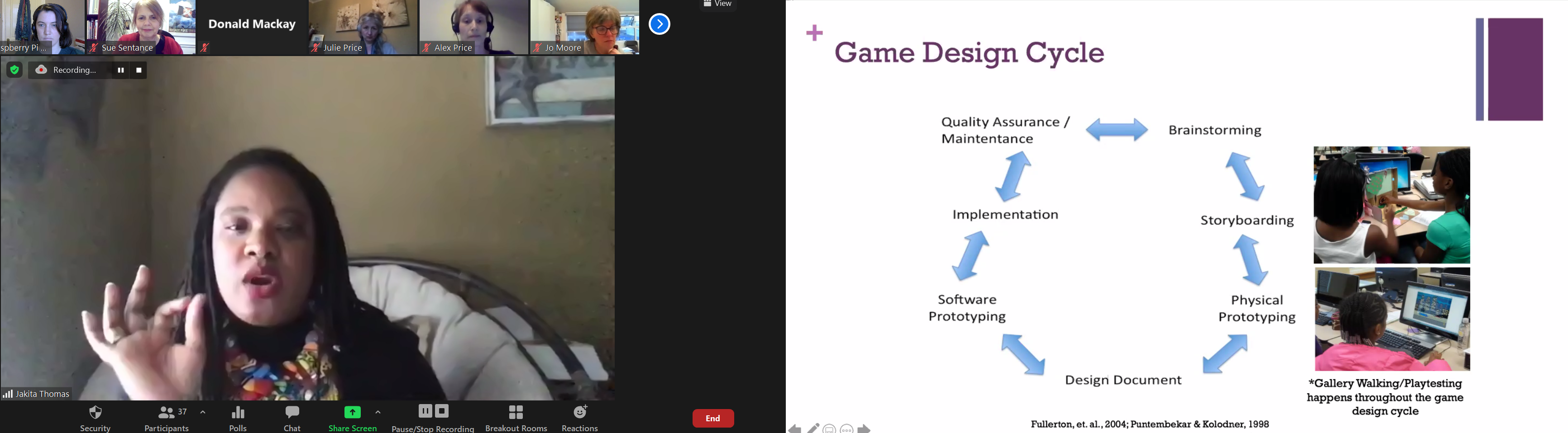
Dr Jakita O. Thomas
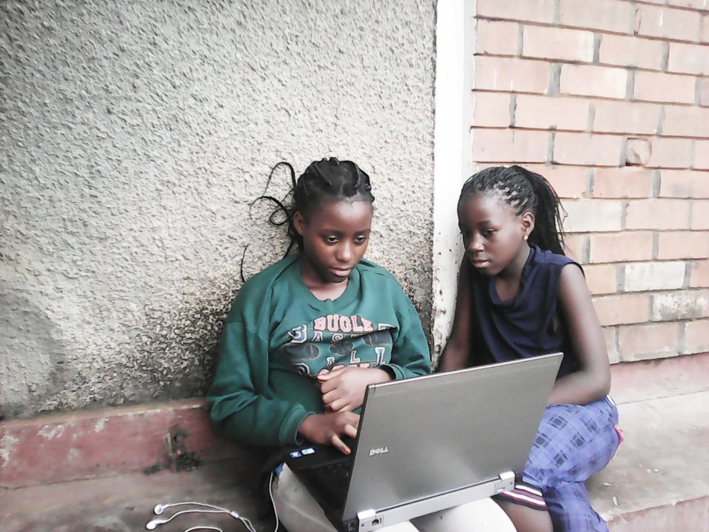
This month we were delighted to hear from Dr Jakita O. Thomas from Auburn University and BlackComputHer, who talked to us about a seven-year qualitative study she conducted with a group of Black girls learning game design. Jakita is an Associate Professor of Computer Science and Software Engineering at Auburn University in Alabama, and Director of the CUlturally and SOcially Relevant (CURSOR) Computing Lab.
The SCAT programme
The Supporting Computational Algorithmic Thinking (SCAT) programme started in 2013 and was originally funded for three years. It was a free enrichment programme exploring how Black middle-school girls develop computational algorithmic thinking skills over time in the context of game design. After three years the funding was extended, giving Jakita and her colleagues the opportunity to continue the intervention with the same group of girls from middle school through to high school graduation (7 years in total). 23 students were recruited onto the programme and retention was extremely high.
Click to enlarge
The SCAT programme ran throughout each academic year and also involved a summer camp element. The programme included three types of activities: the two-week summer camp, twelve monthly workshops, and field trips, all focused on game design. The instructors on the programme were all Black women, either with or working towards doctorates in computer science, serving as role models to the girls.
The theoretical basis of the programme drew on a combination of:
Cognitive apprenticeship, i.e. learning from others with expertise in a particular field
Black Feminist Thought (based on the work of Patricia Hill Collins) as a foundation for valuing Black girls’ knowledge and lived experience as expertise they bring to their learning environment
Intersectionality, i.e. considering the intersection of multiple characteristics, e.g. race and gender
This context highlights that interventions to increase diversity in STEM or computing tend to support mainly white girls or Black and other ethnic minority boys, marginalising Black girls.
Why game design?
Game design was selected as a topic because it is popular with all young people as consumers. According to research Jakita drew on, over 94% of girls in the US aged 12 to 17 play video games, with little differences relating to race or socioeconomic status. However, game design is an industry in which African American women are under-represented. Women represent only 10 to 12% of the game design workforce, and less than 5% of the workforce are African American or Latino people of any gender. Therefore Jakita and her colleagues saw it as an ideal domain to work in with the girls.
Click to enlarge
Another reason for selecting game design as a topic was that it gave the students (the programme calls them scholars) the opportunity to design and create their own artefacts. This allowed the participants to select topics for games that really mattered to them, which Jakita suggested might be related to their own identity, and issues of equity and social justice. This aligns completely with the thoughts expressed by the speakers at our February seminar.
What was learned through SCAT?
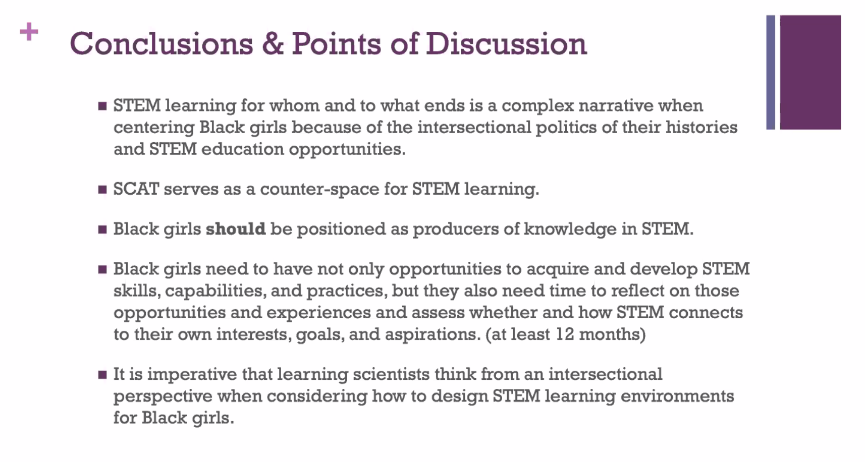
Jakita explained that her findings suggest that the ways in which the SCAT programme was intentionally designed to offer Black girls opportunities to radically shape their identities as producers, innovators and disruptors of deficit perspectives. Deficit perspectives are ones that include implicit assumptions that privilege the values, beliefs, and practices of one group over another. Deficit thinking was a theme in our February seminar with Prof Tia Madkins, Dr Nicol R Howard, and Shomari Jones, and it was interesting to hear more about this.
Data sources of the project included analysis of online journal data and end of season questionnaires across the first three years of SCAT, which provided insights into the participants’ perceptions and feelings about their SCAT experience, their understanding of computational algorithmic thinking, their perceptions of themselves as game designers, and the application of concepts learned within SCAT to other areas of their lives outside of SCAT.
In the first three years of the programme, the number of participants who saw game design as a viable hobby went from 0% to 23% to 45%. Other analysis Jakita and her colleagues performed was qualitative and identified as one theme that the participants wanted to ‘find meaning and relevance in altruism’. The researchers found that the participants started to reflect on their own narrative and identity through the programme. One girl on the programme said:
“At the beginning of SCAT, I didn’t understand why I was there. Then I thought about what I was doing. I was an African American girl learning how to properly learn game design. As I grew over the years in game designing, I gained a strong liking. The SCAT program has gifted me with a new hobby that most women don’t have, and for that I am grateful.”
– SCAT scholar (participant)
Jakita explained that the girls on the programme had formed a sisterhood, in that they came to know each other well and formed a strong and supportive community. In addition, what I found remarkable was the long-term impact of this programme: 22 out of the 23 young women that took part in the programme are now enrolled on STEM degree courses.
Jakita’s final slide, stimulating a great Q&A session (click to enlarge)
This research intervention obviously represents a very small sample, as is often the case with rich, qualitative studies, but there is much we can learn from it, and still much more to be done. In the UK, we do not have any ongoing or previously published research studies that look at intersectionality and computing education, and conducting similar research would be valuable. Jakita and her colleagues worked in the non-formal space, providing opportunities outside the formal curriculum, but throughout the academic year. We need to understand better the affordances of non-formal and formal learning for supporting engagement of learners from underrepresented groups in computing, perhaps particularly in England, where a mandatory computing curriculum from age 5 has been in place since 2014.
Next we’ve got three online events coming up in quick succession! In our seminar on Tuesday 20 April at 17:00–18:30 BST / 12:00–13:30 EDT / 9:00–10:30 PDT / 18:00–19:30 CEST, we’ll welcome Maya Israel from the University of Florida, who will be talking about Universal Design for Learning and computing. On Monday 26 April, we will be hosting a panel discussion on gender balance in computing. And at the seminar on Tuesday 2 May, we will be hearing from Dr Cecily Morrison (Microsoft Research) about computing and learners with visual disabilities.
To join any of these free events, click below and sign up with your name and email address: