Imagine walking through a doorway, and your entrance music begins playing. You’re a pro wrestler, or perhaps a character in a 1940’s hardboiled crime drama? Or the Queen, who no doubt gets to hear the national anthem on a regular basis.
Ty and Gig Builds have a tonne of cool Raspberry Pi projects on their YouTube channel, but we especially liked this one. Why? Because it’s the perfect device to welcome everyone to Raspberry Pi Towers each day. At least, once the time comes to leave our home offices and head back to Pi Towers.
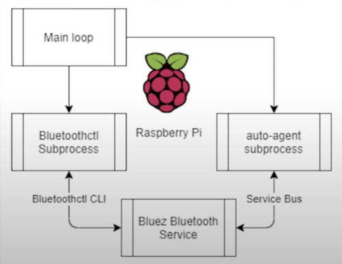
A Python script running on a Raspberry Pi continuously searches for nearby Bluetooth devices in a ‘known’ list. It uses the Bluetooth MAC address of each detected phone in range to determine which entrance music its owner wants. All ‘known’ device owners have already nominated a chosen track, which is stored on the Raspberry Pi, and when it recognises one from its list, the Raspberry Pi plays the owner’s chosen audio file.
Watch Ty and Gig make an entrance to their own songs
Raspberry Pi uses the Bluez stack to communicate over Bluetooth, it’s this service that lets the Raspberry Pi talk to your phone. Ty admits this was the fiddliest part of the build, but he explains it all very clearly, step-by-step, from this point in the video. A sound card, connected via USB, lets Raspberry Pi output audio through a big speaker. But you could also make the sound play through an HDMI TV.
Wanna walk into the house with your own entrance music playing? Here’s the github repo with everything you’ll need. A Raspberry Pi 4 powers this project, but any of our boards with Bluetooth support would work.
You’re also going to need a separate sound card and here’s the one used in this build.
What would your entrance music be?
Some suggestions from the soon-to-return to Raspberry Pi Towers team:
Rob from The MagPi magazine would pick Homer’s entrance music in this
Back in Black, AC/DC
Here You Come Again, Dolly Parton
Paint It, Black, The Rolling Stones
The Imperial March, John Williams
Tiptoe Through the Tulips, Tiny Tim (yes, someone really picked this)
Summer is fast approaching – and that’s the perfect excuse to get building.Whether you want to spy on your local wildlife, upgrade your vegetable patch, or feed your fish when you’re off on a weekend break, Raspberry Pi and a handful of add-ons make a great starting point. The latest issue of The MagPi is packed with some of the most inspirational projects to be found. They include a smart tide monitor, which will tell you when’s the best time to hit the beach, and a clever Heater Meter that can keep an eye on your barbecue while you get on with the prep in the kitchen.
Check the tides
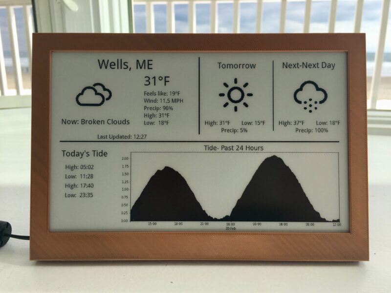
Avoid nasty surprises when you arrive at the beach: check the tide level before you leave home
If you’re heading out for any kind of water-based activity (and that includes sitting on the beach), it helps to know whether the tide is in or out and which way it’s heading. Sam Baker’s neat e-ink tide and weather tracker uses Raspberry Pi Zero and an enormous (7.5 in) e-ink display to track the motion of the ocean and upcoming weather conditions, so you don’t arrive at the beach to find the sand submerged.
Print your own lawn-mower
The return of summer means an addition to your weekly to-do list: mowing the lawn. But not if you build a PiMowBot smart lawn-mower robot. This uses any Raspberry Pi to control an autonomous lawnmower that navigates your garden using GPS and offers optional remote control, so you can keep the lawn trimmed from the comfort of a garden chair.
Sit back, put your feet up, and enjoy the sunshine while PiMowBot takes care of mowing your lawn
The hardware, comprising the chassis, cutterbar and so on, is solar-powered and can be 3D-printed, while the software is a €19.99 download. The OBJ (Wavefront OBJect) file patterns for the various parts you’ll need to print are a £29.46 download from Cults3d. You’ll need to buy several components to put it together, as it also relies on a number of sensors, including – aside from the GPS receiver – a temperature and humidity sensor, compass module, and Camera Module.
Although you do need to invest in quite a few parts for the PiMowBot, and spend time assembling them, the project still manages to undercut (sorry!) commercial alternatives, for which prices start at around £500, by a considerable margin.
BBQ safely
One thing that’s certain to put a dampener on a summer get-together is barbecued food that’s charred on the outside and raw in the middle. Fortunately, a lot of makers have set themselves the task of solving this problem – which they’ve done with aplomb. Tempiture pairs Raspberry Pi with a breadboard, food probe, and a handful of resistors to produce a wireless grilling thermometer which sends readings to the web. As a barbecue can take hours to get to cooking temperature, this lets you keep an eye on its progress while you’re prepping food in the kitchen.
HeaterMeter lets you keep an eye on your BBQ from a distance, freeing you to get on with prep in the kitchen while the HeaterMeter maintains cooking temperatures
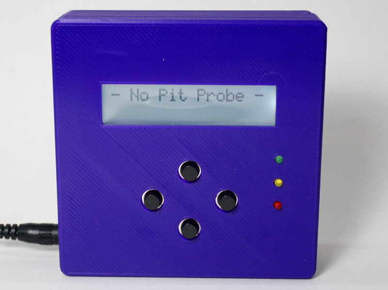
It’s not your only option, either. PitmasterPi performs a very similar job, taking regular readings to populate a real-time dashboard, and optionally sending emails or texts at crucial moments.
HeaterMeter pairs Raspberry Pi with an Adruino microcontroller, thermal probe, and fan to maintain perfect temperatures, with support for web streaming, graphing, and alerts. What’s particularly appealing about HeaterMeter is that you can choose different starting points for your project, depending on how confident you are. If you’re a dab hand at soldering and reading a circuit diagram, start from scratch with a kit; but if you’re just craving a burger, skip all that and opt for a fully assembled board instead.
Build a trail camera
The Naturebytes camera case keeps all the components of an automated bird and wildlife camera neat and tidy
One of the best things about summer is the return of a host of migratory birds that desert us in the colder months. And, while foxes and badgers will have been with us throughout the winter, hedgehogs will have been hibernating between late autumn and early spring. Many of these animals are timid, so spotting them requires that you get up early, stay up late, or set up a trail camera which uses motion detection to capture an image when they pass.
This has been a popular use for Raspberry Pi for years, but there are so many ways to go about it, you might be wondering which are the best options. You can pick up all the parts you need to build your own trail camera – aside from the power supply – from The Pi Hut for £110, or the case on its own for £40 if you have most of the other required components knocking around from old projects.
Get your copy of The Magpi #106 now!
We’ve shared just a few of our favourite summer project ideas here. For the full list, head to page 72 of the latest issue of The MagPi.
You can grab the brand-new issue right now online from the Raspberry Pi Press store, or via our app on Android or iOS. You can also pick it up from supermarkets and newsagents. There’s also a free PDF you can download.
Level up your Guitar Hero gaming with Nick O’Hara’s Jon Bot Jovi Guitar Hero robot. While Nick admits this is an expensive project (around $1000 to build), it’s something that was so “ridiculous, hilarious, and awesome” he felt he just needed to do it.
While you’re not great at Guitar Hero, Nick, you ARE good at making robots
You’re halfway to shredding a Bon Jovi chorus perfectly on Guitar Hero and you can taste the fame. Problem is, you’re no Jon Bon Jovi. Or Peter Frampton. Or Slash. So you need Raspberry Pi to assist your rockstar dreams. Enter Jon Bot Jovi.
A solenoid is just a coil of wire, but when you pass an electric current through it acts as an electromagnet, and a magnetic field is generated. When you turn the current off, the magnetic field goes away. Inside the coil of wire is a metal rod, when the current is on and the magnetic field is present, the rod is free to move in the direction of the field. In this way, a solenoid converts electrical energy into movement and the rod moves in or out of the coil depending on the current applied.
Here, a Raspberry Pi controls a bunch of solenoids as they press and release the buttons on the guitar controller to give Nick his god-like skills. Watch the build video on YouTube for a simple walkthrough of how this all works.
It’s tricky
Building the mechanical fingers and solenoids was one of the trickiest parts of the build. Nick ended up burning through a lot of them as he’s new to robotics and didn’t understand the relationship between power, voltage, and current, so they burnt out quickly. Luckily, he found a robotics guy to give him a 30-minute crash course, which set the project on the right path. Heroes come in all shapes and sizes.
Fret board close-up courtesy of Jeremy Cook on hackster.io
Note recognition was also far from an easy task. Nick originally tried to look at specific pixels on the screen, which worked for slow songs, but for faster songs it would miss around 30% of the notes. He eventually turned to OpenCV, but it took a fair amount of effort to hone the perfect filtering to make the note recognition accurate. Fiddly, but worth it.
Shred, guitar hero!
Nick’s favourite part of the project?
“Seeing Jon Bot Jovi absolutely shred on the guitar. Did you see how fast he’s strumming during Through the Fire and the Flames?!”
We love seeing a maker so happy with a final build and we wish we could come and play too! (We are similarly stunted in our guitar-playing abilities.)
Nick wrote a project post on Hacker News for those who are curious about the more technical details. And the original build video on YouTube is a wild ride, so check it out and subscribe to Nick’s channel.
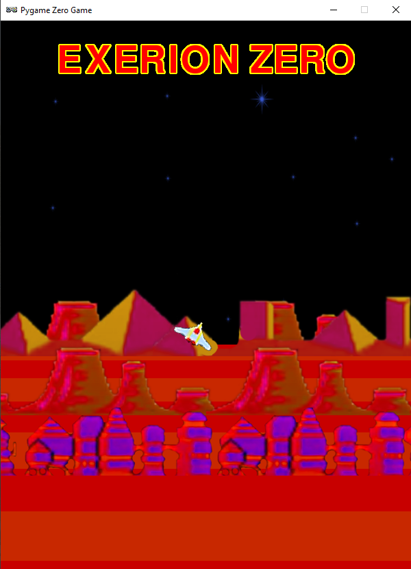
Swoop over mountains in our homage to Jaleco’s shooter. Mark Vanstone has the codein the latest issue of Wireframe magazine, out now.
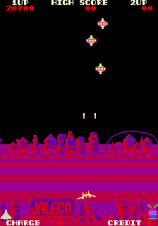
Taking the shooting action of Galaxian from a few years earlier, Japanese developer Jaleco released Exerion in 1983. What helped Exerion stand out from other shoot-’em-ups of the period, though, was its pseudo-3D background, which used both a scrolling landscape and moving background elements to create the illusion of depth. This was quite an achievement considering the hardware of the day, and it’s still an eye-catching effect even now.
Exerion’s pseudo-3D effect helped the game stand out from the crowd of other shooters packed into arcades at the time.
Three main elements
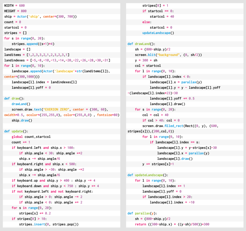
To recreate Exerion’s scrolling in Pygame Zero, we need to break the effect down into three main elements. The first is the scrolling stripes that form the landscape’s base layer. These are followed by the elements that roll over the landscape as it scrolls down the screen. Then thirdly, there’s the player’s movement, which affects both the other two elements. Let’s start with the scrolling landscape, which is made of alternating coloured stripes. To give the sense of perspective, they start very thin on the horizon and, as they move down the screen, they grow in thickness. We can create this with a list that contains the heights of each stripe, increasing as we go through the list. Then in our draw() function, we run through the list, drawing the stripes downwards from the horizon using the heights in our list. Then we increase the height of each stripe. When the first stripe reaches a certain height, we take the last one off the end of the list and add it to the beginning, resetting its height to the smallest.
Our homage to Exerion. You can’t tell from a static image, but the illusion of depth is amazing. Honest.
Landscape details
The next items to code are the landscape details. These are buildings and hills that we want to move with the stripes so that it looks as though the player’s flying over them as they scroll by. We need to do this in two sections as some will be drawn behind the stripes as they’re over the horizon, while others will be in front of the stripes. We’ll give each landscape item an index which ties it to a stripe, but we’ll give items that are beyond the horizon negative indexes, and those in front, positive.
All the landscape items will start with a negative index to indicate that they all start beyond the horizon. So in the draw() function, we have an initial loop to draw all the items behind the horizon, and then while we’re drawing the stripes, we also draw the items which have the same index as the stripes, so they appear in front. Once we have these two parts, we’ll have a continuous carousel of stripes and landscape items.
Player aircraft
Now we need the player aircraft. We can move it around using the arrow keys, but we want to have the background graphics moving to give the impression of a 3D landscape: if the player moves upwards, we move the horizon down, and do the opposite if the player moves downwards. We then apply a parallax effect to the landscape items. The way we do this is by moving the items at the back a small amount in the opposite direction from the player’s movement, and as we work down through the items, they move more and more. This enhances the impression of depth.
Once we’ve added a tilt to the aircraft as it turns, we have the makings of an Exerion clone. All that needs to be added are the aliens to shoot at – if you want to add these, then you could take the Galaxian routine from last month’s Source Code.
Here’s Mark’s code for an Exerion-style, pseudo-3D background. To get it working on your system, you’ll need to install Pygame Zero. And to download the full code and assets, head here.
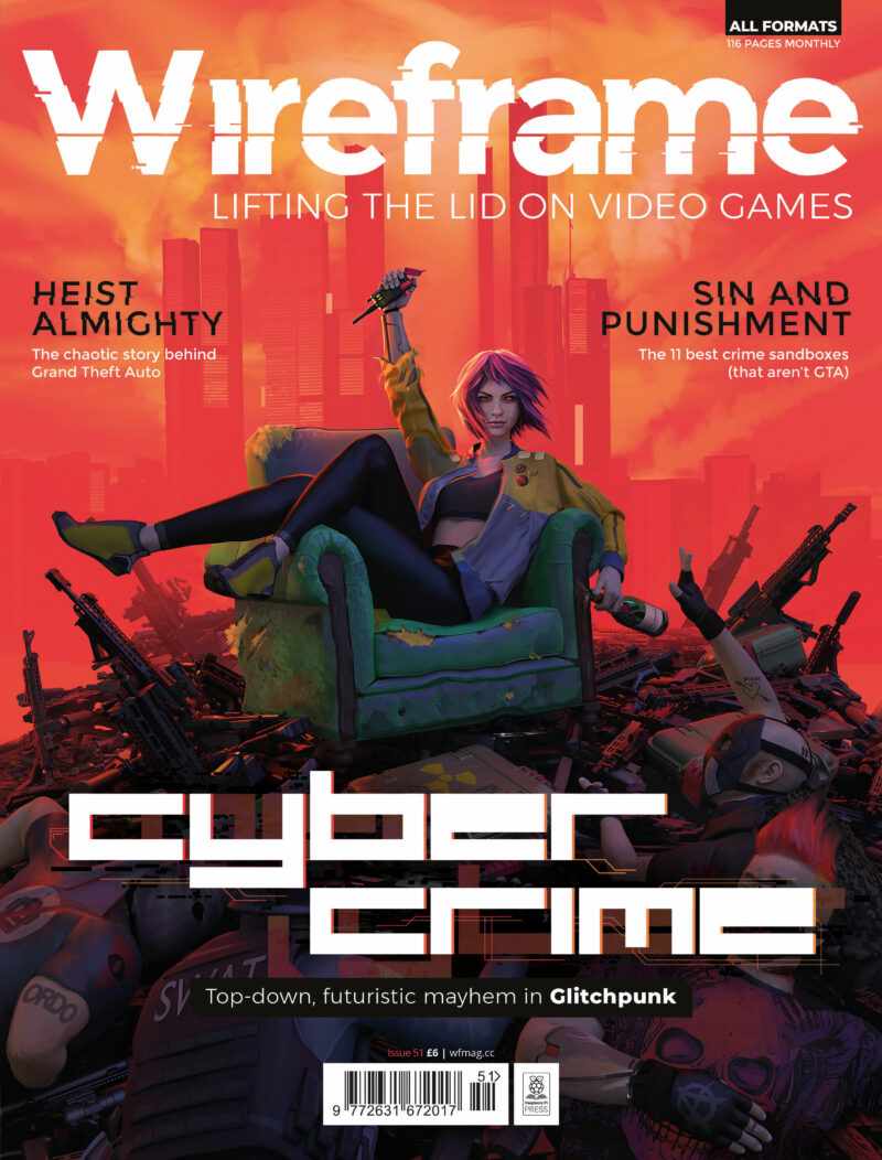
Get your copy of Wireframe issue 51
You can read more features like this one in Wireframe issue 51, available directly from Raspberry Pi Press — we deliver worldwide.
And if you’d like a handy digital version of the magazine, you can also download issue 51 for free in PDF format.
Our team here at the Raspberry Pi Foundation, in collaboration with ESA Education, is excited to announce the successful deployment of young people’s programs aboard the International Space Station (ISS) for the European Astro Pi Challenge 2020/21!
Across both Astro Pi missions — Mission Zero and Mission Space Lab — 14,993 participants created an amazing 9408 programs, which have now run aboard the ISS’s two special Raspberry Pi computers: the Astro Pis Izzy and Ed. Congratulations to all for their achievements during this challenging year!
ESA astronaut Thomas Pesquet congratulates all of this year’s Astro Pi teams
Mission Zero: Popular as ever
This year, 14,054 young people from 24 countries successfully took part in Mission Zero: the Astro Pi computers aboard the ISS ran their programs for 30 seconds each.
In Mission Zero, young people write programs to measure the humidity inside the ISS Columbus module using the Sense HAT add-on of the Astro Pi, and then use the Sense HAT’s LED matrix to display the measurement together with their very own message to the astronauts. This year that included ESA astronaut Thomas Pesquet, who oversaw the deployment of both the Mission Zero and Mission Space Lab programs.
This year’s Mission Zero programs running aboard the ISS
To make it easier for young people to participate in Mission Zero while school closures and restrictions on face-to-face meetings were in place to help stop the spread of coronavirus, we updated the Mission Zero rules this year: for the first time, young people could take part by themselves as well as in teams. As we had hoped, this new option proved hugely popular, with 6308 entries coming from individual participants. Despite the challenging circumstances, this year’s number of Mission Zero participants was just 5% lower than last year’s — a sure sign of how much young people love Astro Pi!
Mission Space Lab: Investigating life in space and on Earth
In addition to the Mission Zero participants, 232 teams of in total 939 students and young people are currently in their final phase of Astro Pi Mission Space Lab. Over the last month, each team had the program for their scientific experiment run on either Astro Pi Ed or Astro Pi Izzy for three hours each.
Photographs of Earth, taken by Astro Pi Izzy aboard the ISS
Teams conducting ‘Life on Earth’ experiments used Astro Pi Izzy’s near-infrared camera to capture images of the planet’s surface. Their experiments include predicting weather patterns by analysing cloud formations, assessing the impact of climate change by investigating reductions in vegetation cover over time using NDVI, and studying variations in the Earth’s magnetic field.
Teams conducting ‘Life in space’ experiments used Astro Pi Ed’s sensors to investigate life inside the ISS Columbus module. Their experiments include measuring the direction and force of gravity inside the Space Station, analysing the air quality onboard, and calculating the position and direction of the Space Station in orbit.
All Mission Space Lab teams have now received their data back from the ISS so they can analyse it and summarise their findings in their final scientific reports. To grant teams enough time to complete their reports while social distancing measures may be in place, we have extended the submission deadline to 12 pm (noon) BST on Monday 28 June 2021!
It’s cosy inside the ISS!
Despite its relatively large size of 109 metres, the ISS only has enough sleeping pods for seven astronauts. However, sometimes there can be more than seven astronauts onboard: usually when one group prepares to leave as another arrives. Recently, a whole eleven astronauts were aboard the ISS, which meant that they had to get creative about where to settle down for sleep.
For Ed and Izzy, our Astro Pi computers, a large crowd such as this can cause some complications! For one thing, ‘crew bumping’ is more likely, which is when the USB cable connecting an Astro Pi to power can become accidentally unplugged because an astronaut collides with it in the small space of the Columbus module. And this time, the snug sleeping situation made one of the crew members request permission to cover Astro Pi Ed’s LED display during the ‘night’! Why? The astronaut was ‘bedding down’ directly opposite Ed, and the light from the display was making sleep difficult! That just goes to show that, even in space, it’s really best to avoid bright light if you need a good night’s sleep.
ESA astronaut Thomas Pesquet with the Astro Pi computers aboard the ISS
Who will win Mission Space Lab 2020/21?
We and our collaborators at ESA Education have appointed a jury of experts to judge all the Mission Space Lab Phase 4 final reports and select the 10 teams with the best reports as the winners of the 2020/21 round of Mission Space Lab. Each of the 10 winning teams will receive a special prize: an invitation to a webinar with an ESA astronaut where they can directly ask them their questions about life in space!
Congratulations again to all the teams that have taken part in the European Astro Pi Challenge this year. Mission Space Lab teams, we can’t wait to read your reports!
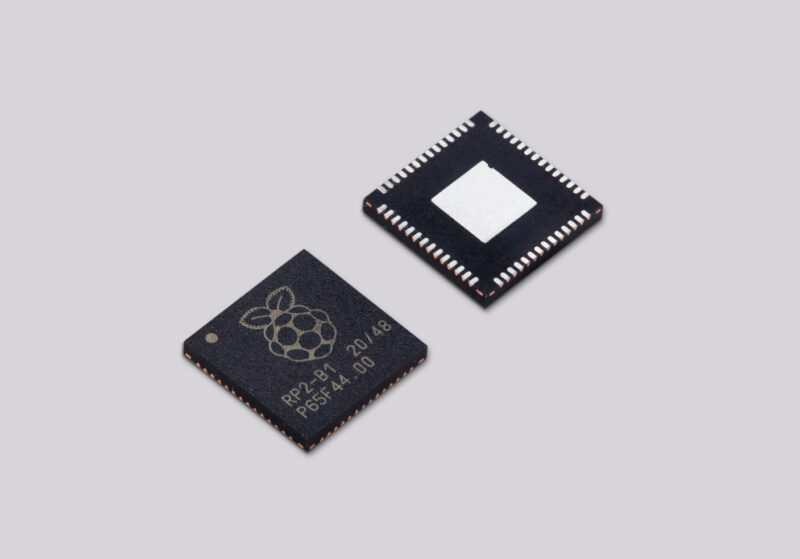
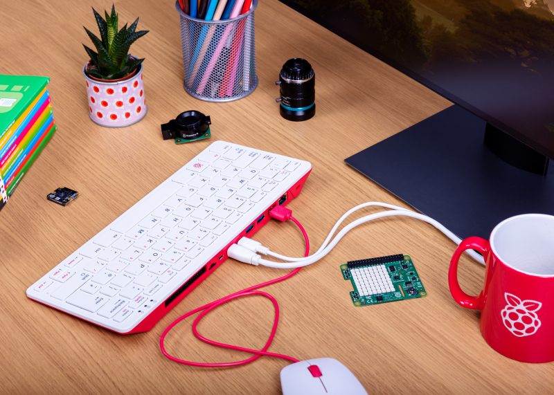
Back in January, we launched Raspberry Pi Pico. This was a new kind of product for us: our first microcontroller-class board, and the first to be built on RP2040, a chip designed here at Raspberry Pi. At the same time, we announced RP2040-based products from our friends at Adafruit, Arduino, Sparkfun, and Pimoroni.
Today, we’re announcing the logical next step: RP2040 chips are now available from our Approved Reseller partners in single-unit quantities, allowing you to build your own projects and products on Raspberry Silicon.
RP2040: the microcontroller, perfected
RP2040 is our idea of the perfect mid-range microcontroller, based on years of using other vendors’ devices in our own products and projects. It stands out in three key ways:
Two fast CPU cores. A pair of ARM Cortex-M0+ cores, clocked at 133 MHz, provide ample integer performance. Use one core to run application code, and the other to supervise hardware; or run application code on both cores with FreeRTOS or MicroPython.
Plenty of RAM. With 264KB of RAM, you can concentrate on implementing features, not optimising your application for size. A fully connected switch connects ARM cores and DMA engines to six independent RAM banks, allowing you to squeeze every last drop of performance out of the system.
Flexible I/O. We provide all the usual interfaces: hardware UARTs, SPI and I2C controllers, USB 1.1, and a four-channel ADC. But it’s the programmable I/O (PIO) subsystem that makes RP2040 stand out, enabling software implementations of protocols including SDIO, DPI, I2S, and even DVI-D.
All of this is packed into 2 mm² of 40 nm silicon, in a 7×7 mm QFN56 package.
Early progress
A lot has happened since January. We’ve shipped over 600,000 Raspberry Pi Picos, and have taken orders for 700,000 more. Graham has continued to build out the SDK, most recently adding FreeRTOS support. And hundreds of people have been in touch asking for RP2040 samples, many via our patented “Secret Twitter Samples Program”. Some of these are maker businesses that have found themselves effectively unable to build products this year due to the global semiconductor shortage.
Aargh. So it seems like maybe we’re doing a samples program in this thread, doesn’t it? I’ve just opened my DMs, so please let me have a shipping address and contact phone number. You too @rpitechguy.
Based on this experience, we’ve decided to pull about 40,000 units of RP2040 out of the supply chain and boot up single-unit sales via our Approved Resellers, roughly three months earlier than we’d intended. This will give people time to develop their projects and products, while we clear out the rest of the Pico backlog and scale up production of RP2040. In the autumn we’ll have some serious volume available for anyone who needs it.
Reely, reely good
The single-unit price of RP2040 is $1, giving you a lot of bang for your (literal) buck. We’re still figuring out what reel-scale pricing will look like in the autumn, but we expect it to be significantly lower than that.
So head on over to the product page to order your first chips. When you’re ready to take your RP2040-based project to scale, we’ll be waiting for you.
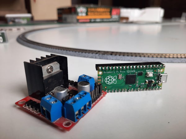
The Orient Express. The Flying Scotsman. Ivor the Engine. All juggernauts of the rail community, but none powered by our microcontroller and all, thus, inferior in our eyes. Raspberry Pi Pico has been used in cooler and more interesting ways every day since its launch in January this year, but this is the first time we’ve seen it powering a miniature railway. KushagraK7 shared this compact application on Instructables, and we ended up down a rabbit hole of model trains enthusiasm.
The Motor Channel on YouTube is a great community for miniature railway enthusiasts
What does Raspberry Pi Pico do here?
KushagraK7’s Raspberry Pi Pico controls the track voltage to control the speed of the train using pulse-width modulation (PWM). PWM is a method of reducing the average power delivered by an electrical signal. A motor driver powers the locomotive itself.
You gotta speed it up and then you gotta slow it down
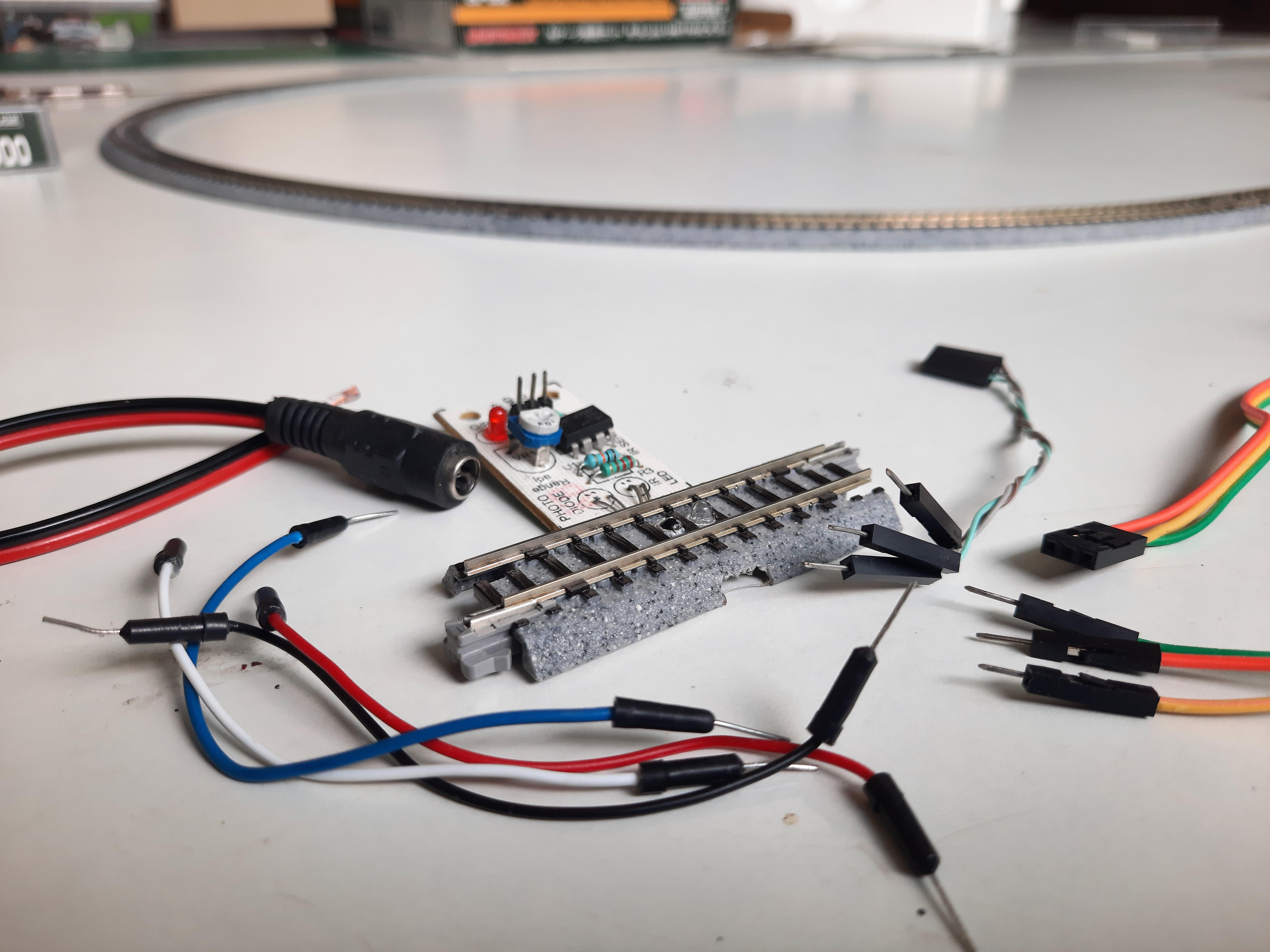
This particular setup is designed to make the train start off slowly then speed up gradually each time it travels over a sensored segment of the track — that is, a segment equipped with an infrared sensor to detect whether a train is there. A therapeutic loop of the speeding-up process plays from this point in KushagraK7’s YouTube video.
The ‘sensored’ part of the train track ready to be connected
Once the train reaches its top speed, it slows down again, coming to a complete halt after it passes the sensored track section once more. The train stops for a set amount of time, then starts up again. Fast, faster, slow, stop. Fast, faster, slow, stop. And on and on and on again. All without any human interaction needed – you can just watch. Super satisfying.
Learn how to make a low-cost sensored track “in minutes” with this previous Instructable from the maker
How do I build it?
KushagraK7 has created an illustrated step-by-step tutorial for other miniature railway enthusiasts to follow, including when you should tidy up your wires, plus ideas to tinker with the code to adjust speed and stopping patterns.
Point us to your Raspberry Pi-powered model railway projects in the comments. Choo choooooooo.
Here’s an ingenious way of using a Raspberry Pi to calculate pi – and why not? Nicola King runs the numbers in the latest issue of The MagPi magazine.
Pi is an irrational number, which means it can’t be expressed as the ratio of two integers.Since it has an infinite number of decimal places, calculating it to ever greater accuracy has long been an objective of mathematicians. So what better project for Pi Day (14 March) than to get a Raspberry Pi to calculate pi?
That’s what Adrian Chung reckoned when looking to create a project for a ‘speed round’ contest. “I thought it would be neat to use a Raspberry Pi to compute pi to arbitrarily high precision,” he tells us.
After looking into various methods, he learned about a class of algorithms that differed from the usual summing up of a sequence of decimal approximations. “Intriguingly, these so-called ‘spigot algorithms’ computed the next digit of pi after every few iterations of applying a small set of operations on a handful of integers,” he notes.
Numbers on tap
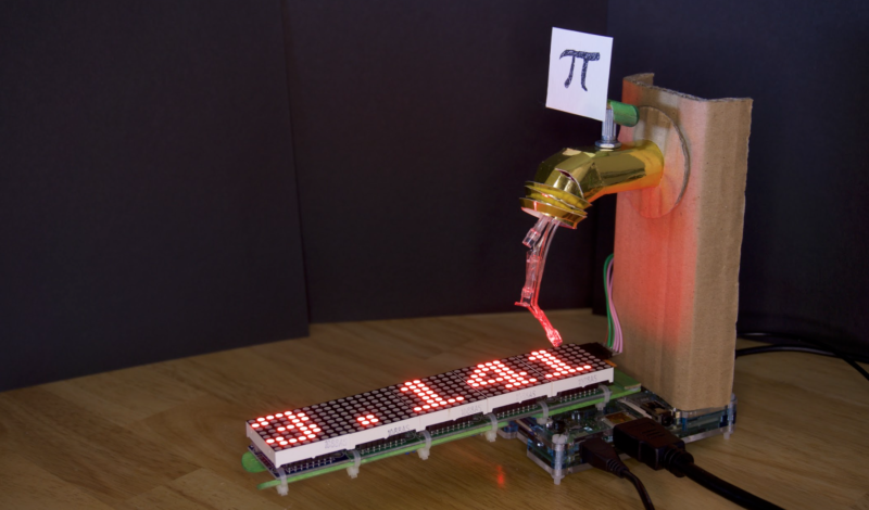
Rather than simply using a Raspberry Pi to compute pi with a spigot algorithm, Adrian thought it required a more visual approach. “The need for a more visually explicit indication of what was actually running on the Raspberry Pi gave me the idea of creating a physical spigot prop with a tactile check valve that can be used to pause or resume the iterations of the algorithm,” he explains. Upon the user turning the spigot, digits appear to flow from the tap and along an LED matrix display below.
An animation of three LEDs creates the illusion of digits flowing from the tap
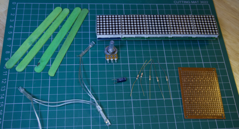
“The MAX7219 8×8 LED display modules are daisy-chained SPI devices that are hooked up to the SPI interface on Raspberry Pi,” says Adrian. “They are powered directly off the 5V rail; however, I had to add a separate power switch because they power up with all the LEDs turned on and this was pulling down the supply voltage during bootup.”
Three GPIO pins are used to animate the LED drips from the spigot. “The LEDs were cut from a Poundland Christmas decoration. Current is limited by 150 Ω resistors so that the drips don’t appear overly bright against the scrolling display.”
A close-up of the spigot, which is constructed from shiny gold card with a cardboard stand
A potentiometer in the spigot is connected to two GPIO pins to check the valve position. “This works by using one pin to charge a capacitor through the potentiometer, forming an RC delay, and then timing how long until a logic high is read by the other pin.”
Adjusting the flow
Adrian adapted an existing scrolling text demo script in the luma.led_matrix source code library: “I had to choreograph the dripping LED animation with the previous digits scrolling off to the left and the reveal of a new digit under the spigot.”
He also needed to alter the potentiometer reading script, replacing the simple timing loop with regular system time queries for greater accuracy.
Additional components for the build include resistors, a capacitor, and perfboard
So, how accurately can his Raspberry Pi Spigot calculate pi? “I left it to run for about six hours,” says Adrian. “It computed more than the first 8000 digits. It can compute pi much faster than this, but the animation of the digits streaming from the spigot would just be a blur.
“Because those integer variables in the spigot algorithm only get larger, they continue to consume more and more RAM as more digits are cranked out. I don’t really know how many digits of pi my 1GB Raspberry Pi 2 would have been able to calculate if I had just let it run.”
Whatever the answer, the project has proved a hit with the community: Adrian’s original tweet video has over 10,000 views and was retweeted over 100 times.
Get your copy of The Magpi #106 now!
You can grab the brand-new issue right now from the Raspberry Pi Press store, or via our app on Android or iOS. You can also pick it up from supermarkets and newsagents. There’s also a free PDF you can download.
In this article from the latest issue of HackSpace magazine, Rob Miles takes a look at debugging.You’ll find what a debugger does and discover how to add hardware that can be used to tell us what our devices are really thinking.
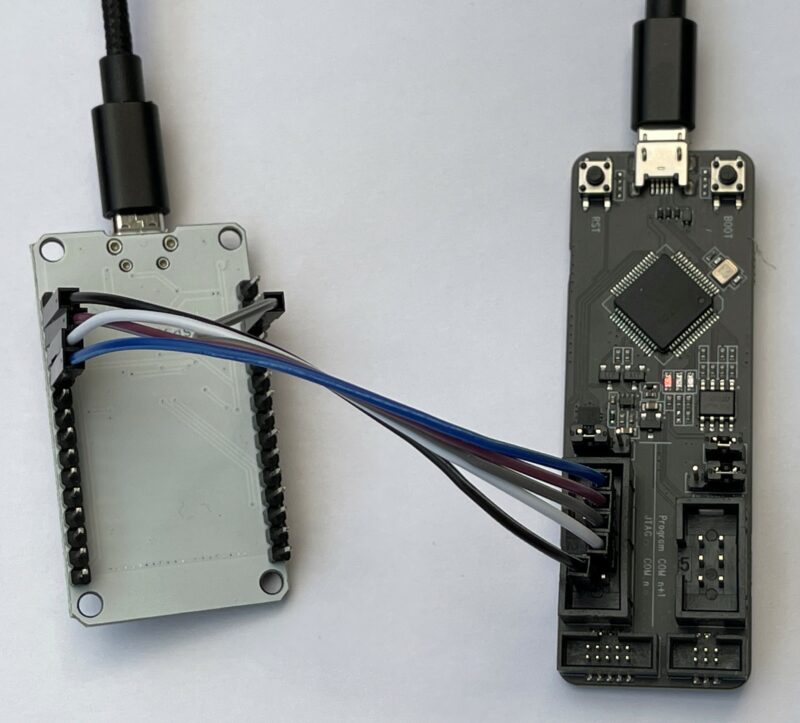
Figure 1: An ESP32-PROG (on the right) connected to a DOIT ESP32 device using direct connection to the JTAG pins
Bug origins
Whenever your program doesn’t do what you want it to, you’ve got a bug. An early bug was an insect that got stuck in the contacts of an early computer. Bugs can be caused by many things, including poor specification, programmer error, or plain bad luck. The very first programmers had no way of fixing their bugs other than staring at their code and trying to work out what had gone wrong. However, if you are writing a program on a desktop computer today, one of the tools at your disposal will be your trusty debugger. This allows you to stop a program, look at what it is doing, and then continue, or even step through individual program statements.
Building code for debugging
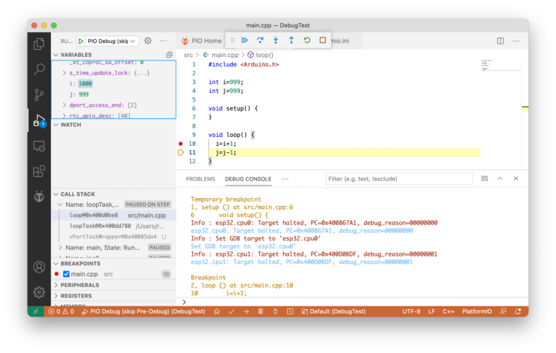
To understand how a debugger works, we can start by considering the compilation process. Some languages, including C++, are compiled. A program called a compiler converts program source code into low-level machine code which tells the hardware what to do. This machine code is loaded into the target computer which runs your code. To see how this works, consider the following loop function.
void loop() {
  i = i + 1;
  j = j  - 1;
}
Each time theloop function is called, it will add 1 to the value in the variable i and subtract 1 from the value in the variable j. We might want to run this function on an ESP32 device. This can’t understand C++ statements, so the compiler converts them into a sequence of instructions that it can understand.
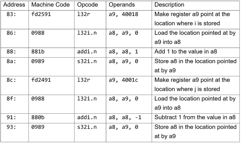
In the Figure 2 table, you can see the instructions produced by the compiler for the statements in the loop function. They have been simplified slightly and a description added. The first column shows the address in memory of that instruction. Computers store programs and data in numbered locations. When a program is running, the processor takes machine code instructions from a location and performs them. It then moves down memory to the next instruction. The instructions from the loop function are stored in memory starting at location number 83.
Figure 2: ESP32 Assembler table
The second column shows the machine code values stored in the ESP32. The first instruction is made up of three bytes which have the values 0xfd (in hex), 0x25, and 0x92. When the program is running, the ESP32 decodes and performs these instructions.
The opcode column contains the name of the operator, and the operands are the things that the operator works on. The opcode and operands columns aren’t needed by the ESP32: it only needs the machine code bytes. Those two columns are just for us to read. From them, we can work out that the variable i is being held in location 40018, and the variable j is held in location 4001C. It is also worth noting that the ESP32 performs subtraction by adding a negative number.
Breaking in is hard to do
If the loop function above is not doing what we think it should be, then we can look at the values in i and j each time it runs. One way to do this would be to replace the machine code instruction at location 83 with an instruction that jumps into some debugging code that we can use to view the contents of our variables. When the program reaches this statement in the program, it would enter our debugger. This is called setting a breakpoint in the code. The debugger could show the contents of the registers and then we could tell the debugger to jump back into the loop function and continue execution of our program.
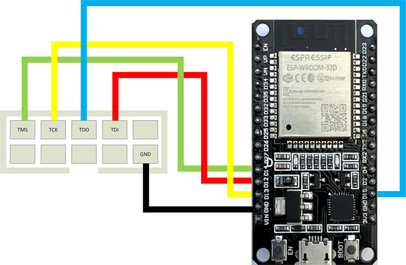
Figure 3: Wiring diagram for connecting an ESP32‑PROG (left) to a DOIT ESP32 (right)
To create a breakpoint, the debugger program uses information provided by the compiler which tells the debugger where all the variables are stored and the location of each program statement. This information is produced when a program is compiled in ‘debug’ mode. The debugger uses this to work out where to insert the breakpoint code that will pause the program. This works well if the debugger is running on the same computer as the program being debugged. However, when we are writing programs for an embedded device, this is not the case. ESP32 code is sent from our computer into the target device to run. There is no way that the debugger can set a breakpoint by modifying the program code because it doesn’t have access to it. So, how can we put breakpoints into code running inside an embedded device?
We’ve been expecting you, Mr Bond
In the early days of embedded development, developers used versions of processors called ‘bond-out’ devices. These were special versions of processors which brought out the internal signals, including the address lines that identified the memory location that the hardware was accessing at any given instant. These chips were made by ‘bonding’ extra wires to the internal circuitry, hence the name.
Developers used hardware that monitored the addresses being used and detected when particular locations were being read or written. This extra hardware, called an ‘in-circuit emulator’, was the only way to debug early embedded code. To debug our loop function, we would tell the hardware to stop the device when it detected an attempt to read from the program memory at address 83 (where the machine code for the loop function starts). The circuitry would then read the registers in the device and allow us to view their contents. This method worked well, but the emulators were expensive and only large companies could afford them.
Figure 04: Debugging with Visual Studio Code
Enter JTAG
As the power and complexity of microprocessors grew, it became harder to make bond-outs to expose all the internal signals that make hardware debugging possible. To address this, manufacturers formed a Joint Tag Action Group (JTAG) to define standards by which a device can expose its internal state using just a few pins.
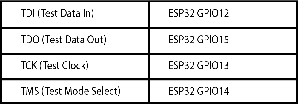
Many circuit boards have pins labelled JTAG which are used during manufacture and testing. Sometimes these pins can also be used for hardware debugging. Not all processors support hardware debugging connections. The ATmega328P processor used in the Arduino Uno cannot be debugged in this way. However, the ESP32 does provide these connections. Some of the general-purpose input/output (GPIO) pins on an ESP32 can be used as JTAG connectors. To debug code running in hardware, you’ll need some way of connecting your development computer to the JTAG signals on the target device. Espressif (the same company that makes the ESP32) produces a great device for this. It is called the ESP32-PROG.
The ESP32-PROG
You can pick up an ESP32-PROG device for around £15 or so. It can also be used to program an ESP32. It can be connected via a ribbon cable or you can use DuPont cables (socket to socket), as shown in Figure 1.
The table above shows the connections between an ESP32 and the ESP-PROG device.
Figure 3 shows how the socket on the ESP-PROG can be connected to an ESP32 device. Note that both the ESP32 and the ESP-PROG will need to be connected to a power source via their micro USB connectors. You will still deploy your program using a connection to the ESP32 device. If you encounter problems with program deployment, disconnect the ESP32 USB cable from your PC and try again.
The OpenOCD connection
The debugging itself is managed by the ‘Open On-Chip Debugger’ (OpenOCD) software. This provides a connection between the hardware and the software environment that you use to write and debug your code. OpenOCD talks to the ESP-PROG device over USB. The ESP-PROG provides two serial port connections to the host computer. One can be used for programming an ESP32 via the 6-pin connector on the ESP-PROG. The other is used to control debugging.
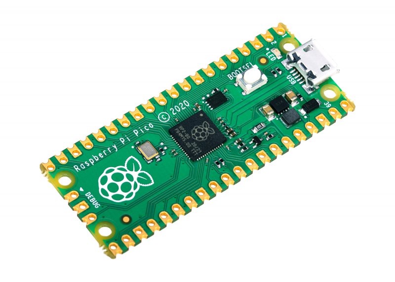
The three pins on the bottom edge of Pico are for connecting a debugger
Debugging with Visual Studio Code and PlatformIO
Visual Studio Code is a free development environment that runs on PC, Mac, and Raspberry Pi. PlatformIO is a free plug-in for embedded development using Visual Studio Code. PlatformIO includes the OpenOCD framework. A PlatformIO project contains a platform.ini file that contains the project configuration options. We need to edit this file and add two lines to our configuration:
Now we can open up the debug window in Visual Studio Code and start the debugger.
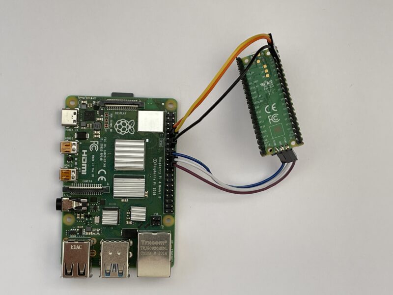
This shows how to connect a Pico to a Raspberry Pi for program deployment and debugging. You will need to add a USB power source to the Pico, as the connections shown are just for data
Hardware debugging with Raspberry Pi PICO
The Raspberry Pi Pico device exposes JTAG signals that can be used for hardware debugging. You can wire these directly to a Raspberry Pi and use that as the debugging and development platform, or you can use another Raspberry Pi Pico device as a debugging probe.
The Pico documentation gives detailed instructions on how to do this here. You can use the GNU Debugger to debug a program from the command line.
(gdb) b main
Breakpoint 1 at 0x1000035c: file /home/pi/pico/pico-examples/blink/blink.c, line 9.
(gdb) continue
Continuing.
Thread 1 hit Breakpoint 1, main () at /home/pi/pico/pico-examples/blink/blink.c:9
9       int main() {
(gdb) step
14          gpio_init(LED_PIN);
The statements above are from a GDB debug session investigating the blink demo program for the Pico. The debugging commands that were entered are shown in bold. You can see a breakpoint being set on the main method, and then the program stepping on from the breakpoint to the first statement which initialises the LED. If you want to use Visual Studio Code to debug your programs on Raspberry Pi, you can do this as well.
Hardware debugging for the win
Hardware debugging is very powerful. It lets you look inside your devices to see exactly what they are doing. You do need to be a bit careful when you use it sometimes, because the debugging process stops the target device and all background processes. On a device like the ESP32, this can cause problems with WiFi and Bluetooth connections being maintained during debugging. However, given the low cost of getting started, you should definitely consider adding the technique to your armoury of tools.
Issue 43 of HackSpace magazine is on sale NOW!
Each month, HackSpace magazine brings you the best projects, tips, tricks and tutorials from the makersphere. You can get it from the Raspberry Pi Press online store or your local newsagents.
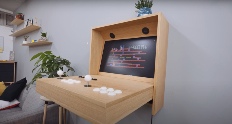
Alexandre’s goal was to build something that looks like an ordinary piece of furniture, and that you’d have no idea is an arcade machine until you flip it open. It’s a fully functional two-player device and it requires no coding skills to set up.
Big build
It’s a big piece of furniture, so you’ll need a big space and a good table saw to get all the wood cut. Alexandre made the whole thing out of just one piece of oak plywood. He’s a woodwork perfectionist, and didn’t want any visible screws on the finished product, so he had to get fancy with biscuit joints. He also ironed on edge banding, to give an extra-smooth finish to the rough cuts of plywood.
Master carpenter in his giant workshop
Hardware
The electronics for the build arrived by way of a complete kit containing everything needed to make the joysticks and buttons. The kit came with a little circuit board which all the buttons and joysticks plug into, and the output is a simple USB which connects to the Raspberry Pi brain of the system.
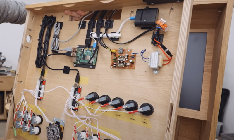
Raspberry Pi and wiring for buttons and joystick all tucked away in the back of the wooden frame
Parts list
(These are all links to the actual products used in this project)
Alexandre had never used a Raspberry Pi before, but still found the electronics the easiest part of this build.
Retro gaming easily accessible in your home
This tutorial video made it easy to load up RetroPie software on the Raspberry Pi’s SD card and get some games onto a USB stick. And this video showed him how to run games from a USB device.
Sleek design
Everything is so neatly tucked away in this design. A slot for the USB cable and a Raspberry Pi reset switch are built into the wooden frame, so absolutely none of the electronics are on show.
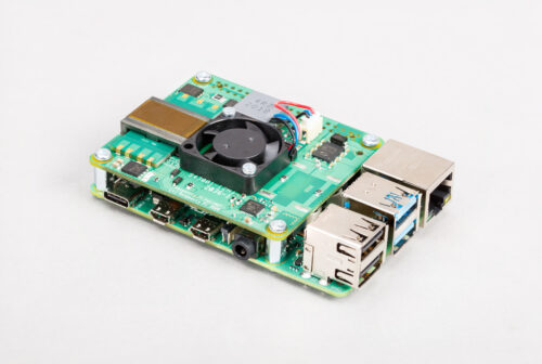
Today we’re announcing the next generation of our Power over Ethernet (PoE) HAT. Compared to its predecessor, the Raspberry Pi PoE+ HAT delivers more power, implementing the 802.11at PoE+ standard; and it runs cooler, thanks to various design improvements. Best of all, we’ve been able to keep the original affordable price of $20.
PoE HAT TNG
The current global semiconductor shortage — which you’ll almost certainly have read about by now — is constraining our supply of the original PoE HAT. In general, we’re weathering the shortage very well, and the supply of mainline Raspberry Pi computers, Zeros and our other products have not been affected (we’re very good at pipelining). Unfortunately, the first-gen PoE HAT uses silicon that’s in short supply.
The old HAT will remain in production, but we are taking the unusual step of announcing this new product before we have stock in channel, so that industrial customers can consider migrating to the new PoE+ HAT, which will have shorter lead times. The Raspberry Pi PoE+ HAT will be available from our Approved Resellers in early June. (Visit our Products page to be automatically directed to your local Approved Reseller when you select a product.)
Power (over Ethernet) to the people
One of the coolest features we’ve added to Raspberry Pi in the last few years has been Power over Ethernet (PoE) support. From Raspberry Pi 3B+ onward, we use an Ethernet jack with the appropriate taps on its windings, and connect those taps to an additional 4-pin header, located just beneath the top-right mounting hole. A HAT can pick up these signals, request power from the switch, and regulate the resulting 37-57V DC down to 5V to power the Raspberry Pi.
At the end of 2018, we released the Raspberry Pi PoE HAT, which did just this. After some embarrassing teething troubles, it has become one of our best-selling accessories. We’ve seen it used in industrial applications like digital signage and factory automation, and by hobbyists who want to put their Raspberry Pi somewhere remote, sharing a single cable for both power and data.
More power
The original PoE HAT implements the 802.3af standard, and can deliver a guaranteed minimum of 13W to the Raspberry Pi. This is enough to power a Raspberry Pi 4 at maximum load, but not quite enough to power the hungriest USB peripherals at the same time.
The PoE+ HAT implements the 802.3at standard. When used with a compatible switch or injector this means it can deliver up to 25W, as you can see from this comparison table.
PoE HAT
PoE+ HAT
Standards supported
802.3af
802.3af, 802.3at
Output voltage
5V
5V
Maximum output current
2.5A
5A
Maximum power
15.4W
25.5W
Fan
Yes
Yes
Current sense
No
Yes
Transformer design
Wire-wound
Planar
PCB
4 layers, 2oz copper
4 layers, 2oz copper
Price
$20
$20
Compatible with
Raspberry Pi 3B+, 4B
Raspberry Pi 3B+, 4B
A better diode rectifier
What else has changed? To reduce heat dissipation we replaced the diode rectifier with an “ideal diode” rectifier, in the form of a Microchip PD70224ILQ device.
Thermal image of PoE+ HAT delivering 2.5A
A shiny new transformer
PoE implementations require a transformer to provide voltage conversion and isolation. When you think of a transformer, you probably think of wire wrapped around a ferrite core, and this is exactly what the original PoE HAT uses. For the PoE+ HAT, our friends at Bourns have provided us with a shiny new toy: a planar transformer.
Bourns planar transformer
As you can see from this disassembled version, in a planar transformer the “windings” are actually traces on a multi-layer PCB; the ferrite is assembled around the PCB. The result is a slimmer transformer (useful if you really care about z-height and are prepared to dispense with the fan) which is more suitable for surface-mount assembly. And it has the added benefit of looking like an artefact from the future.
Like something off the Starship Enterprise
We think you’ll notice a real improvement over the original and much-loved PoE HAT. We’re always fascinated to learn what work users end up putting their Raspberry Pis and accessories to — if you’re doing something particularly cool with PoE, let us know!
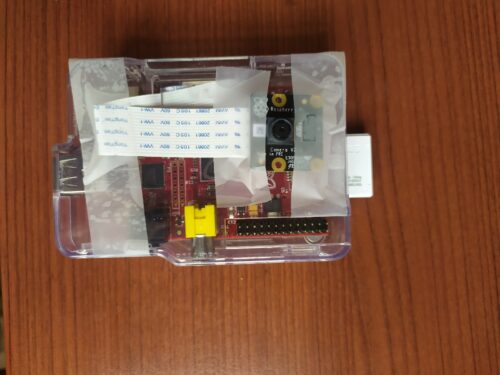
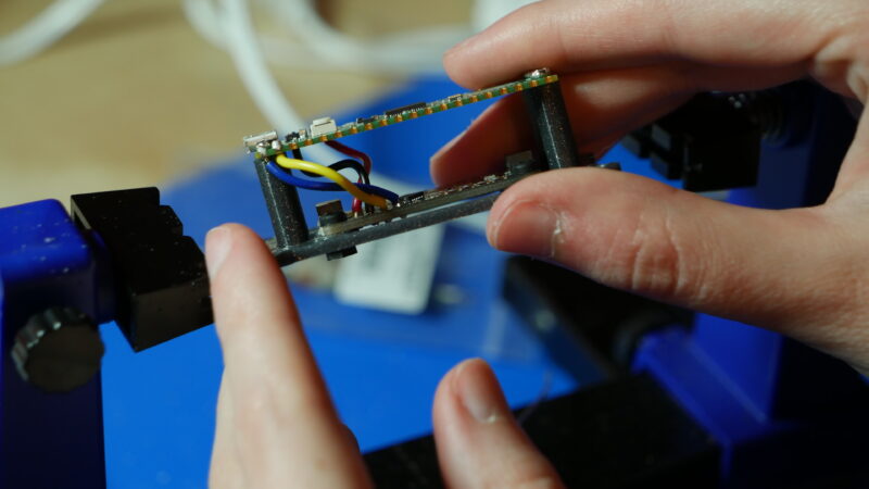
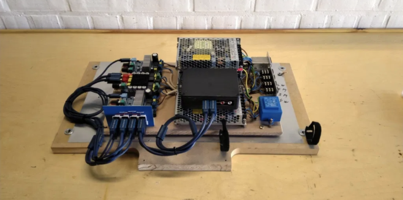
Driver drowsiness detection was the original application for this project, and Raspberry Pi was chosen for it because it’s small enough to not obstruct a driver’s view and can be powered from a vehicle’s 12 V socket or a USB port.
Teeny tiny setup
Our Raspberry Pi NoIR Camera has no infrared filter and can therefore detect infrared light. It was chosen for this project to help with driver visibility by infrared illumination in low light, because night time is when people are more likely to become drowsy.
Never drive tired
Firstly, you should absolutely never drive tired. The UK’s Driver and Vehicle Licensing Agency says that, by law, after every 5 hours 30 minutes of driving you must take a break of at least 30 minutes.
We’re sharing this project because we like the software behind this sleepiness detector, which can tell when your eyes narrow and alert you before you nod off. A safer application of this invention could be for exam cramming season when you don’t want to fall asleep before reading that final chapter of your revision guide. Or perhaps for the sleepier among us who need extra help staying awake for the New Year’s Eve countdown. We cannot miss another one of those. But we get SO sleepy.
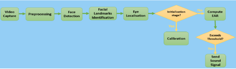
How does SleePi work?
How SleepPi uses EAR to detect sleepiness in the eyes
The camera tracks the position of the eyes and uses something called the Eye Aspect Ratio (EAR) to detect blinks. When squinting or blinking is observed, Raspberry Pi thinks you’re getting sleepy. When sleepiness is detected, a loud alarm sounds via the Raspberry Pi’s AUX port, connected to the car’s speaker system. The alarm carries on sounding until the camera detects that the user’s eyes are completely open again.
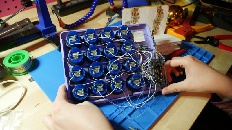
MIDI Fighter-style controllers (MIDI controllers with grids of arcade buttons) have been a staple of the DIY MIDI controller community for years. This project, featured in the latest issue of HackSpace magazine, continues that tradition with the Raspberry Pi Pico. A grid of 16 arcade buttons lets you play MIDI notes faster than you can yell “Hadouken!”, either live with hardware or with your digital audio workstation (DAW) of choice.
Do you think they painted the studio bright pink especially? Perfect match for the purple MIDI
The Pico is the perfect board for a project like this. With all the GPIO pins, you can directly wire your inputs and outputs without issue. The copious GPIO also allows this MIDI controller to have some special features. There is a screen with a GUI representing the 4×4 button grid, along with the assigned MIDI note numbers. Below the screen is a five-way navigation switch that allows you to select the individual buttons and adjust their MIDI note number on the fly rather than having to adjust the code.
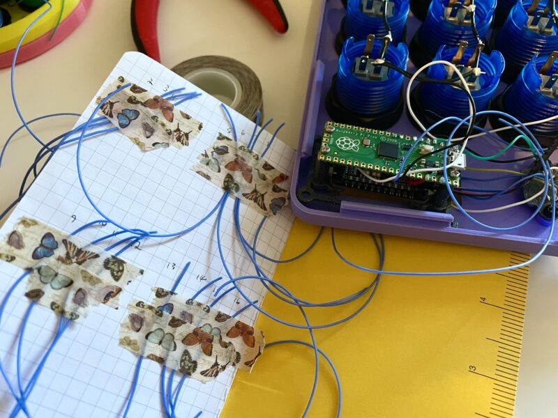
Need more buttons? Add a GPIO expander
Finally, there is an AW9523 expander board for control over the arcade buttons’ LEDs. Both the screen and AW9523 are Adafruit STEMMA boards, which means they can be chained together to work over I2C.
Of course, there are some parts of this project that are optional, like the buttons’ LEDs and the screen. Feel free to use this build as a jumping-off point for a simpler MIDI controller or change up some of the features to better suit your needs.
All the grounds get connected together
Inspiration
Noé Ruiz and I love to collaborate on projects together. We’ve worked on a few MIDI projects in the past, and had discussed wanting to do a MIDI Fighter at some point. The MIDI Fighter-style controller also has a special place in my maker heart, since it was my very first DIY MIDI project that I worked on a few years ago. It had code written with Arduino, and was one of my first big soldering projects as well.
When the Raspberry Pi Pico came out, Noé and I thought it would be perfect for a MIDI Fighter, since it had so many GPIO. Noé also wanted to add another feature: the ability to change MIDI notes on the fly instead of having to edit the code. Noé is an accomplished beat drummer and felt that this feature would streamline his live drumming process when working on a beat with his DAW and software instruments. I was excited for the challenge to implement that feature and code up a user-friendly GUI. I think that it really makes this version of the classic MIDI Fighter-style controller stand out from the crowd.
Usage
The Raspberry Pi Pico MIDI Fighter has features that make it ideal for both playing live and noodling at home working on a track. You can use it with your computer’s DAW over USB and change the assigned MIDI notes on the fly for different settings or to different note input options. The fast and accurate nature of the arcade buttons makes them great candidates for live beat making and performance.
3D printed standoffs make assembly easy
For more on this project’s 3D-printed case, assembly and code, head to page 52 of the latest issue of HackSpace magazine.
And an in-depth, step-by-step tutorial by Liz Clark and Noé Ruiz is available on the Adafruit Learning System.
Issue 43 of HackSpace magazine is on sale NOW!
Each month, HackSpace magazine brings you the best projects, tips, tricks and tutorials from the makersphere. You can get it from the Raspberry Pi Press online store or your local newsagents.
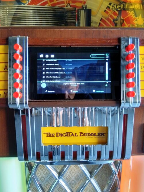
It’s been a while since we saw a good jukebox retrofit project, so when we saw this old Wurlitzer transformed into a modern, all-in digital jukebox, we had to share it.
Maker Marc Engrie’s cousin came across an old Wurlitzer on a local online second-hand store. The seller had imported it from the US and intended to convert it himself but never got round to it, so he ended up selling it on. Marc’s cousin enticed him with some photos of the Wurlitzer and asked how much it would cost him to breathe new life into the jukebox.
Name your price
Marc already had three Raspberry Pis at home running music streaming software Volumio, so he felt confident he could harness the power of our tiny computer to bring this classic objet d’art back to life. Adding on hardware costs, he figured he could restore it to its former glory for €600 (about £500).
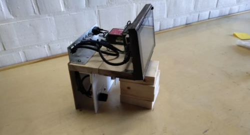
Once the jukebox was delivered, Marc stripped everything away, including the unfinished work of the previous restorer. The iconic enclosure was all that was left, along with the loudspeakers.
Adding new hardware
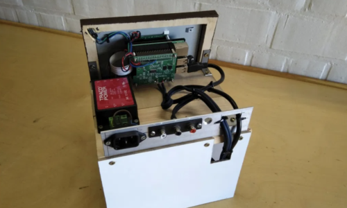
A 2GB Raspberry Pi 4 and a Raspberry Pi Touch Display form the new brain and face of the Wurlitzer. HiFiBerry‘s DAC+ Pro allows music to play from a USB stick. Other devices can play music from an auxiliary-in port.
The two sides of the new face of the jukebox
Marc added a 2 x 2-channel audio amp (2 x 100W for the woofers plus 2 x 100W for mid/high). It’s easy to install and uninstall in case the jukebox ever needs repairing.
And as a final modern finishing touch, he swapped all the original lights for LEDs.
NEAT wire control
Lots of docs
Marc is a super diligent maker and has crafted a spreadsheet showing all the hardware, prices, and retailers. You can also get your hands on a comprehensive software setup instructions, as well as a hardware map showing you how all the Wurlitzer’s new insides fit together. Better still, there’s a whole user manual showing you how every single button and switch works. We think his middle name should be ‘Thorough’. Super, top, detailed job, Marc.
Play me!
See more from Marc
Check out more of Marc’s electronics projects here. There’s a weather station, an automated greenhouse, a chicken shed with an automatic door, and more.
When Stack Overflow conducted a survey of 64,000 software engineers, it found that 1% of their respondents were blind — a far higher percentage than among the total population. Yet it is far from easy for young people with visual disabilities to engage in learning programming in school. In this month’s seminar, Dr Cecily Morrison of Microsoft Research Cambridge shared some of her work in this area. Her talk highlighted the difficulties that children learning to program face if they are blind or have low vision, and the affordances of physical programming tools, in particular Code Jumper.
Dr Cecily Morrison
In her work as a Principal Researcher, Cecily focuses on designing inclusive experiences for people who are blind or have low vision, and she is leading the team that designed Code Jumper (known as Project Torino during its development). She is currently engaged in developing assistive agent technology in Project Tokyo, and she was recently awarded an MBE for her services to inclusive design.
Block-based programming is inaccessible for children with visual disabilities
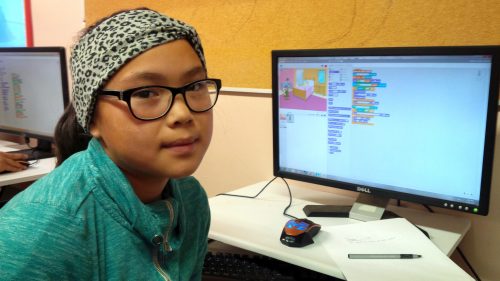
Block-based programming has become the norm for primary school-aged children who are learning to program, and a variety of freely available environments exist, e.g. Scratch and Blockly. These tools have lots of advantages: discoverability of commands; no syntax errors; and live, imaginative visualisations. But how do you use Scratch if you are blind or have low vision and cannot see the screen?
Block-based programming environments are commonly used to teach children about programming.
There are tools that ‘read out’ code in blocks-based environments but — as we experienced in the seminar — their audio output may not readily facilitate understanding. Listening to one line of code at a time can be difficult, for example when trying to understand a loop (let alone a nested loop!). It puts significant demand on listeners’ memory, and children may lack the conceptual cognitive structures to process the audio information. In addition, using screen-based programming environments involves other challenges for blind children: they need to master touch typing, memorise keyboard shortcuts, and understand file systems.
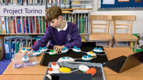
Project Torino to Code Jumper
To address these challenges, Cecily’s team at Microsoft Research started to develop a physical programming tool for primary-aged learners, in a project known as Project Torino. The project started in 2015, and the tool was developed iteratively over the next four years. The team’s goal for this research project was always to generate a tool that is useful and available to all young learners who are blind or have low vision. Thus, in 2019 the research and technology was transferred to the American Printing House for the Blind, and the Project Torino tool was renamed Code Jumper.
As learners listen to the physical programming tool’s program output, they can can follow the execution of the program using their hands.
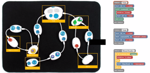
In the seminar Cecily described the iterative development of the physical programming tool. It consists of a number of physical pods, including a play pod, rest pod, loop pod, and selection pod. The young learner can feel the difference between the pods by touch and link them together in the right sequence to construct a program. They then use a central pod, known as the hub, to play an audio output of the program they have created. Using this tool they can code tunes, songs, and stories using ready-made sound sets or sounds that they record themselves.
Dials on the pods allow learners to change the parameter values for each program statement, e.g. the number of times to loop. The parameters can also be changed programmatically through the insertion of ‘plugs’ into the dials. For example, a ‘random’ plug can get a random sound to play.
A use case example is coding the song Row, row, row your boat, which is a common nursery rhyme in the UK and USA. By attaching different pods and using the dials, a learner can use a loop to play “row” three times, and then can add pods for the sounds for “your boat”. Constructing a program like this helps the young programmer learn about sequencing and loops.
Several threads can be attached to the central hub, as in the image below, so that children can learn to use multi-threaded programming, as they can in block-based programming environments such as Scratch. The seminar recording below includes some examples of Code Jumper in action!
Code Jumper supports multi-threaded programming.
Five design principles
Cecily described five design principles that her Microsoft Research team used while developing this physical programming tool:
Persistent program behaviour — When you listen to a program one block/line at a time, it’s hard to get a sense of what it does. Therefore, an important requirement in the design process was that the tool should allow the user to experience the program as a whole. With Code Jumper, the young person can use their hands to follow the program as it executes.
Liveness — This refers to the responsiveness of the tool. It was important to have instant feedback when programming: with Code Jumper, as soon as you touch one of the pods, you get a response.
Low floor, high ceiling — This means the tool is accessible to absolute beginners, but it also offers the opportunity to write more complex programs and develop more advanced skills.
Works across visual abilities — The tool can be used by children with and without vision, and it was designed to be used by learners with multiple disabilities as well as those with low vision.
Enables progression — The tool can support learners moving from a physical language to a textual language, by enabling them to listen or read their code as they follow its execution.
The ultimate aim of Code Jumper is to open career opportunities in technology.
Evaluation of the tool
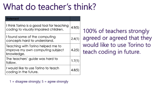
As part of Cecily’s research project, her team undertook a nationwide trial to evaluate the effectiveness of Project Torino, with 75 children and 30 teachers. The trial involved a diverse group of students with a wide range of cognitive skills, and the teachers mostly didn’t have much computing experience.
The team developed a curriculum and sent the teachers full course materials along with Torino kits and laptops. A validated instrument was used to measure engagement and motivation, along with teacher-reported learning outcomes.
In the findings from the trial, all teachers (100%) said that they would like to continue using Torino. Students were also very engaged by the project. Students’ self-efficacy in coding grew substantially after exposure to Torino, with a change in the median score from 2 to 4 (of 5) and large effect size (r = -0.730).
Cecily presented findings from the Torino trial showing the teachers’ responses to the assessment questionnaire.
Among the qualitative data the team collected, the teacher-reported outcomes included comments about the young people’s use of programming vocabulary (see our previous seminar on the importance of talk in learning to program), and how they improved their problem solving skills. Some teachers also commented on the fact that the physical computing tool generated an inclusive environment in the classroom, as it allowed sighted and non-sighted children to work together.
Overall, our seminar audience found this a very interesting and engaging topic and had lots of questions for Cecily in the question-and-answer session. There is obviously much more to do to ensure that computing is accessible to all children, regardless of any disability or impairment. Research projects such as the one Cecily presented generate useful output in terms of tools for use in the classroom or home, and they also challenge us to think about all our learning materials and their accessibility.
Between January and July 2021, we’re partnering with the Royal Academy of Engineering to host speakers from the UK and USA to give a series of research seminars focused on diversity and inclusion. By diversity, we mean any dimension that can be used to differentiate groups and people from one another. This might be, for example, age, gender, socio-economic status, disability, ethnicity, religion, nationality, or sexuality. The aim of inclusion is to embrace all people irrespective of difference.
In our next research seminar on Tuesday 1 June at 17:00–18:30 BST / 12:00–13:30 EDT / 9:00–10:30 PDT / 18:00–19:30 CEST, we’ll welcome Dr Hayley Leonard and Thom Kunkeler from the Raspberry Pi Foundation team. They will be talking about ‘Why the digital divide does not stop at access: understanding the complex interactions between socioeconomic disadvantage and computing education’.
To join this free event, click below and sign up with your name and email address:
Keza MacDonald has been a video games journalist and critic for more than 15 years, and is currently video games editor at The Guardian. In the latest issue of Wireframe magazine, she tells us how her love affair with the Japanese gaming industry started.
When I was a kid, Japan was synonymous with video games. Unlike the home-computer-raised British children of the 1980s, I grew up with Nintendo (and, more reluctantly, with Sega), and later with PlayStation. My first console was a SNES, my second an N64, my third a PlayStation 2, and my fourth a Dreamcast bought on the cheap just after it was discontinued, and all of my formative gaming experiences were Japanese.
I’m not just talking about the obvious stuff, though naturally Mario, Zelda, and Pokémon were a huge part of my childhood. I used to sit and peruse issues of Super Play and N64 Magazine in the magazine aisle of the supermarket whilst my dad did the weekly shop, poring over tiny screenshots of mysterious imported Japanese games like 64 Ōzumō and Harvest Moon. For my N64, I didn’t buy GoldenEye (primarily because my mum wouldn’t let me, but still) – I bought Konami’s Mystical Ninja Starring Goemon, a bizarre musical RPG set in a surreal Edo-period-inspired Japan. I bought Treasure’s bizarre action game, Mischief Makers. On Dreamcast, my introduction to Sega consisted of Space Channel 5, Shenmue, and Crazy Taxi.
Later on, as a teenager, I became a bit of a specialist in digging out obscure Japanese games on the PlayStation 2 and GameCube. I played bizarre evolution game Cubivore, innovative music game Mojib-Ribbon, even more innovative musical shooter Rez, and Chulip (a game about arriving in a new town and working your way up to kissing the girl of your dreams, starting with kissing the upside-down gimp hanging around in the sewer). I discovered, and very quickly became obsessed with, Bemani games like Guitar Freaks and Dance Dance Revolution. I loved the diversity and creativity of Japanese games, and the fact that I often encountered something entirely unexpected in them. Having grown up in a different culture, the language of their cultural references and their sense of humour was intriguingly new to me.
I learned katakana as a teen so that I could read basic menus and muddle my way through imported games. Later, at university, I studied Japanese so that I could spend a year abroad; when I landed in Nagoya, a city on the coast between Tokyo and Kyoto where I spent some of the happiest and most fun months of my life, I remember being weirded out by a sense of déjà vu. I kind of had been there before, but only in games like Shenmue. I had a great time exploring arcades, spending most of my money on random bargain-bin N64 games, travelling the country, and being extremely laissez-faire with my actual studying.
This was in 2008, and what I was witnessing was the tail-end of Japan’s cultural domination of video games. My favourite Shibuya arcade has closed now. Some of the others I used to frequent are still there, but increasingly full of UFO grabbers rather than old Street Fighter cabinets or mysterious rhythm-action games. Shooters and open-world games were becoming the dominant genres, and Japan did neither of them well. Ahead of Keiji Inafune’s famous proclamation that Japan’s games industry was dead in 2009, The “Is Japan over?” op-eds had already started, as the publishers and developers that made many of the weirdest games of my childhood started to fold, the industry started to globalise, and online play became the norm.
Since then, indie games have had a resurgence, but Japan has never developed a particularly robust indie scene. Its games industry still revolves around the huge companies that forged it. We’ve still got Nintendo, Capcom, and Square Enix, but others like Konami and Sega are shadows of their former selves, and we’ve lost Sony’s Japan Studio among many others. Japan hasn’t been at the epicentre of the games industry for many years now. But for those who grew up when I did, it will always be its true home.
Get your copy of Wireframe issue 50
You can read more features like this one in Wireframe issue 50, available directly from Raspberry Pi Press — we deliver worldwide.
And if you’d like a handy digital version of the magazine, you can also download issue 50 for free in PDF format.
The latest event in the Raspberry Pi Foundation series of research seminars was our first panel discussion, with formal and non-formal learning opportunities in computing education and their impact on gender balance as its theme.
The panel was chaired by Dr Yota Dimitriadi, Associate Professor of Computing at the University of Reading, who was joined by four expert speakers: Dr Jill Denner, Senior Research Scientist at ETR; Amali de Alwis MBE, Managing Director at Microsoft Startups and Founder of Code First: Girls; Pete Marshman FCCT, NCCE Computing Hub Leader at Park House School; and Carrie Anne Philbin MBE, Director of Education Products here at the Raspberry Pi Foundation. The event opened with lightning talks from all speakers, followed by an interactive question-and-answer section. Our audience learned from a blend of research insights and lived experiences about practical ways to promote gender balance in both formal and non-formal computing education.
Broadening the tech sector employee pool and empowering all students to see computing as a life-changing, fulfilling subject remains an enduring issue in many countries around the world. In England, the proportion of girls choosing formal qualifications in computer science is slowly increasing, and a number of initiatives support the uptake of computing as a career for girls and women. Nevertheless, much remains to be done in order to present computing as an appealing option for girls. In this blog post, I present three key themes which were covered during the panel session. You can find the recording of the event at the bottom of the post.
Theme 1: Putting computing in context
Students often describe computing as a very abstract, academic subject. Dr Jill Denner shared that research has shown a promising approach to altering this perception: connecting the content of computing lessons to people’s everyday lives. Learners’ need for contextual lessons was reiterated by Pete Marshman. In his teaching, Pete has observed that the very first lesson in Year 7 (11-year-olds) is crucial, because students form opinions about computing immediately. Pete devised a lesson that uses collaborative play and pixel art to introduce steganography, a cybersecurity technique for hiding data in plain sight within an ordinary file or message.
Pete’s very first lesson for 11-year-old students gives them a real-world context for computing
Computing education research has much more to uncover about how computing can be presented as a relevant subject in formal education. In this vein, Carrie Anne Philbin gave an overview of the Relevance strand of the ground-breaking Gender Balance in Computing research programme (co-led by the Foundation). The programme’s Relevance strand will explore the impact of linking computing to real-world problem-solving, working with Year 8 pupils in more than 180 secondary schools in England.
Theme 2: Giving everyone a sense of belonging
A second theme that emerged during the panel discussion was to who belongs in computing, more specifically which groups self-identify as belonging in computing. Computing suffers from the perception of brilliance bias amongst students: they often feel that they need genius-like abilities in order to succeed with their computing studies, and that such abilities are most commonly exhibited by men. Amali de Alwis turned this concept upside down when she described the “human-centred design” of Code First: Girls courses. Women attending these courses learn from a volunteer with a group of peers and become part of a community where members support each other towards brilliance. Jill echoed this when she spoke about the need to challenge stereotypes, embed diversity in educational materials, and continue to educate teachers to create computing classrooms where girls feel that they belong.
You can find out more about embedding diversity in computing lessons from our past research seminar about equity-focused teaching.
In the Belonging strand of the Gender Balance in Computing programme, the researchers will look closely at the attitudes of both boys and girls towards computing, and Carrie Annie explained that giving learners the chance to talk to female role models from the tech sector may cause a measurable shift in their attitudes to the subject. Pete highlighted practical steps that every school can take by using internal role models drawn from the student body to inspire other pupils and produce influential peer-to-peer interactions. As Jill remarked so succinctly, educators need “to tell all students they belong in computer science”.
Theme 3: Presenting learners with role models and advocates
Finally, we heard about the role that adult and course leader expectations play in shaping young people’s attitudes towards computing. Eccles’ expectancy-value theory suggests that when girls and women make choices about a subject (or career), they are influenced by the perceptions that others hold about that subject. If parents, teachers, and course leaders unconsciously discourage girls from considering computing, then girls will take notice of this. However, adults also have opportunities to underline that they see the value of computing, as for example a parent from Pete’s school did by accompanying a school trip to Google’s offices. In non-formal learning spaces, educators can share insights about their own approaches to problem-solving in computing, such as learning from others’ code on GitHub. Amali believes that sharing this type of common workplace practice shows that in the tech sector you are not expected to be able to solve every problem alone, which helps girls and women feel that they can succeed in a computing career.
For learners it’s very important to have role models, such as the inspiring young programmer Dalia Awad, who was a guest on our Digital Making at Home live stream recently.
Final takeaways
The drop-off in female participation in computing between formal education and the workplace has often been presented as a leaky pipeline. This deficit-based model suggests that solutions need to be aimed at fixing the leaks in the pipeline, such as providing interventions at specific stages when girls make decisions about formal qualifications or careers. An alternative viewpoint and important takeaway from the panel was this: as a community of educators and researchers, we need to focus our efforts on identifying the unconscious bias that exists in computing education, so that we can dismantle the barriers that this bias has created and ensure girls have access to equitable computing education at all stages of their learning.
During the question-and answer-session, Dr Yota Dimitriadi skillfully drew out and linked some key factors to encourage girls and women to flourish in computing. The audience heard about the need for advocates at all levels in schools to support careful and thoughtful timetabling of computing lessons. Questions about overcoming negative learning experiences and succeeding later in life elicited thoughts from the panel about how non-formal learning can break down learners’ preconceived ideas about computing and show that it’s never too late to learn.
Watch the recording of the event here:
More research is urgently needed
A recent report from Engineering UK suggests that one possible impact of the coronavirus pandemic is a widening of the existing gender gap in young people’s engineering or technology career aspirations. That means the need to promote gender-equitable learning spaces in both formal and non-formal computing education is even more pressing now.
Research to provide evidence-informed solutions will be absolutely crucial to shifting the gender balance in computing. The Raspberry Pi Foundation is a lead organisation in the Gender Balance in Computing research programme, funded by the Department for Education to identify scalable approaches to improving the gender balance in computing. We are currently recruiting primary and secondary schools in England to take part in trials starting in September 2021 and January 2022. Sign up or find information to share with your networks.
Next up in our free series
In our next research seminar on Tuesday 1 June at 17:00–18:30 BST / 12:00–13:30 EDT / 9:00–10:30 PDT / 18:00–19:30 CEST, we’ll welcome Dr Hayley Leonard and Thom Kunkeler from the Raspberry Pi Foundation team. They will be talking about ‘Why the digital divide does not stop at access: understanding the complex interactions between socioeconomic disadvantage and computing education’. To join this free event, click below and sign up with your name and email address:
There is growing momentum behind the idea of putting computing, computer science, and digital making at the heart of modern education. At the Raspberry Pi Foundation, we want to connect with and support computing educators, both inside and outside of the classroom. Hello World magazine, which we started in 2017, is a platform to help educators all over the world to find inspiration, share experiences, and learn from one another. Hello World is free and has proven to be very popular, with subscribers hailing from 172 countries across the globe!
Hello World, coming directly to your ears now
The Hello World community has told us that they’re hungry for more content while they wait for each new magazine issue. So to complement the magazine, we’ve launched a brand-new Hello World podcast to meet this need! That means you can now hear directly from the educators who are writing Hello World articles, dive a little deeper, and have some fun along the way.
Guests Cat Lamin and Neil Rickus speaking to Hello World podcast hosts Carrie Anne Philbin and James Robinson about well-being and technology
In season 1 of the Hello World podcast, you will:
Explore the importance of creativity and passion in computing with PBS Digital Innovator and CUE Rock Star Amanda Haughs
Dive into the role of ethics in computing with Isaac Computer Science content creator Diane Dowling
Discover how to look after our well-being while teaching with technology, with practical tips from computing educator Cat Lamin and senior lecturer in computing education at the University of Hertfordshire Neil Rickus
Get answers to the question “Are these the droids you’re looking for to teach algorithms?” with computing teacher Huzaifah Zainon and advanced skills computing teacher Nicki Cooper
Listen and subscribe wherever you get your podcasts
Start listening to our first episodes now, wherever you usually get your podcasts. And make sure to subscribe to never miss an episode!
* {
box-sizing: border-box;
}
.header {
text-align: center;
padding: 32px;
}
.row {
display: -ms-flexbox; /* IE10 */
display: flex;
-ms-flex-wrap: wrap; /* IE10 */
flex-wrap: wrap;
padding: 0 4px;
vertical-align: top;
text-align: center;
align-items: flex-start
}
/* Create four equal columns that sits next to each other */
.column {
-ms-flex: 33%; /* IE10 */
flex: 33%;
max-width: 33%;
padding: 0 4px;
align-items: flex-start
}
.column img {
margin-top: 0px;
vertical-align: top;
width: 100%;
}
.column figure {
margin-top: 0px;
vertical-align: top;
}
/* Responsive layout – makes a two column-layout instead of four columns */
@media screen and (max-width: 900px) {
.column {
-ms-flex: 50%;
flex: 50%;
max-width: 50%;
}
}
/* Responsive layout – makes the two columns stack on top of each other instead of next to each other */
@media screen and (max-width: 400px) {
.column {
-ms-flex: 100%;
flex: 100%;
max-width: 100%;
}
}
Let us know if you have a question or a topic you would like us to explore on the Hello World podcast. You can get even more involved by featuring as a guest on a future episode, sharing your top tips and best teaching practices with computing educators around the world. Get in touch with us at podcast@helloworld.cc with your suggestions!
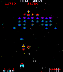
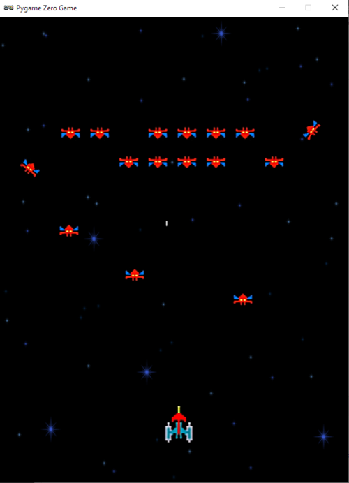
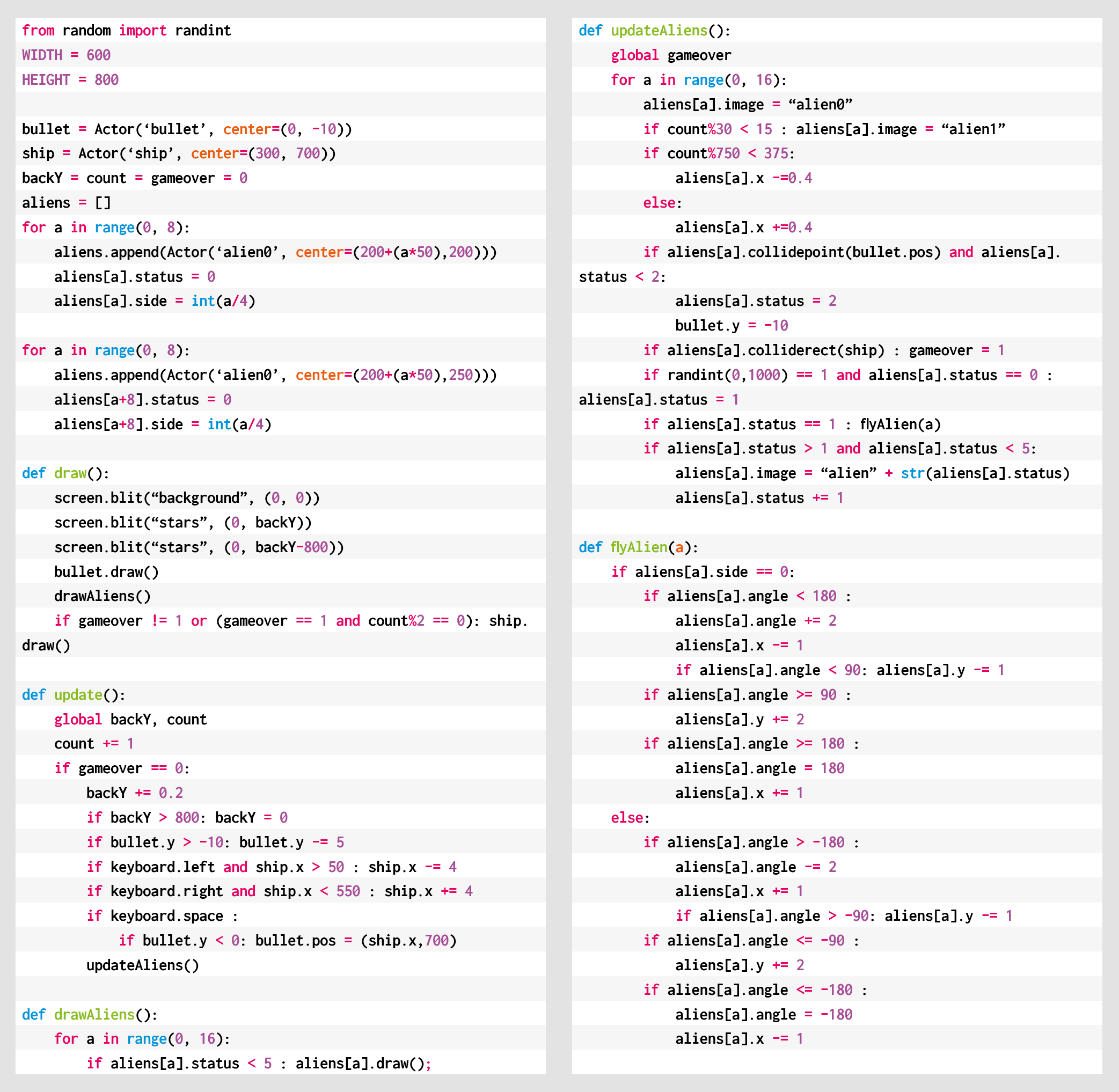
Blast dive-bombing aliens in our salute to Namco’s classic. Mark Vanstone has the code
Aliens swoop down towards the player, bombing as they go. Back in 1979, this was a big step forward from Taito’s Space Invaders.
Hot on the heels of the original Space Invaders, Galaxian emerged as a rival space shooter in 1979. Released by Namco, Galaxian brought new colour and unpredictable motion to the alien enemy, who would swoop down on the defending player. Galaxian was so popular in arcades that Namco released a sequel, Galaga, two years later – that game complicated the attack patterns even more. It’s difficult to say how many ports and clones have been made of Galaxian, as there are several versions of similar games for almost every home platform.
The player’s role in Galaxian is similar to Space Invaders, in that they pilot a ship and need to destroy a fleet of aliens. With Galaxian, however, the aliens have a habit of breaking formation and swooping down towards the player’s ship, and dive-bombing it. The aim is to destroy all the enemy ships and move on to the next wave. The subsequent waves of enemies get more difficult as the player progresses. For this sample, we’re going to look at that swooping mechanic, and make the bare nuts and bolts of a Galaxian game with Pygame Zero.
Our homage to the classic Galaxian, with angry aliens that love to break formation.
First, Galaxian has a portrait display, so we can set the play area’s width and height to be 600 and 800 respectively. Next, we can create a scrolling backdrop of stars using a bitmap that we blit to the screen and move downwards every update. We need a second blit of the stars to fill in the space that the first one leaves as it scrolls down, and we could also have another static background image behind them, which will provide a sense of depth.
Next, we set up the player ship as an Actor, and we’ll capture the left and right arrow keys in the update() function to move the ship left and right on the screen. We can also fire off a bullet with the SPACE bar, which will travel up the screen until it hits an alien or goes off the top of the screen. As in the original Galaxian, you can only shoot one bullet at a time, so we only need one Actor for this.
The aliens are arranged in rows and move left and right across the screen together. We’ll stick to just one type of alien for this sample, but draw two rows of them. You could add extra types and any number of rows. When we create the alien Actors, we can also add a status flag, and we need to determine which side of the row they’re on as when they break formation, the two sides fly in opposite directions. In this case, there’ll be four aliens on the left of each row and four on the right. Once they’re set up in a list, we can iterate through the list on each update and move them backwards and forwards. While we’re moving our aliens, we can also check to see if they’ve collided with a bullet or the player ship. If the collision is with a bullet, the alien cycles through a few frames of an explosion using the status flag, and then, when their status reaches five, they’re no longer drawn. If the collision is with the player, then the player dies and the game’s over. We can also check a random number to see if the alien will start a bombing run; if so, we set the status to one, which will start calls to the flyAlien() function. This function checks which side the alien’s on and starts changing the alien’s angle, depending on the side. It also alters the x and y coordinates, depending on the angle. We’ve written this section in longhand for clarity, but this could be collapsed down a bit with the use of some multiplier variables for the x coordinates and the angles.
There we have it: the basics of Galaxian. Can you flesh it out into a full game?
Here’s Mark’s code for a Galaxian-style shooter with attacking groups of aliens. To get it working on your system, you’ll need to install Pygame Zero. And to download the full code and assets, head here.
Get your copy of Wireframe issue 50
You can read more features like this one in Wireframe issue 50, available directly from Raspberry Pi Press — we deliver worldwide.
And if you’d like a handy digital version of the magazine, you can also download issue 50 for free in PDF format.
Fancy some extra PC hardware, overclocking, gaming and modding content in your life this summer? You can get your hands on a FREE PDF download of each new Custom PC magazine issue released during May through to September.
You’ll find stuff like in-depth hardware reviews and step-by-step photo guides, as well as hard-hitting tech opinion, game reviews, and all manner of computer hobbyism goodness.
Our favourite regular feature is Retro Tech, so we’re sharing this latest one by Stuart Andrews to get you started on your summer of love with Custom PC.
Forgive the blocky pixels and 16-colour palette. In Catacombs 3-D and Catacombs: Abyss lay the seeds of Wolfenstein and Doom
Pity the poor PC of 1983-1984. It wasn’t the graphics powerhouse we know today. IBM’s machines and their clones might have been the talk of the business world, but they were stuck with text-only displays or low-definition bitmap graphics. The maximum colour graphics resolution was 320 x 200, with colours limited to four from a hard-wired palette of 16. Worse, three of those colours were cyan, brown and magenta, and half of them were just lighter variations of the other half.
By this point, IBM’s Color Graphics Adaptor (CGA) standard was looking embarrassing. Even home computers such as the Commodore 64 could display 16-colour graphics, and Apple was about to launch the Apple IIc, which could hit 560 x 192 with 16 colours. IBM had introduced the Monochrome Display Adaptor (MDA) standard, but this couldn’t dish out more pixels, only higher-resolution mono text.
Meanwhile, add-in-cards, such as the Hercules or Plantronics Colorplus, introduced higher resolutions, but did nothing for colour depth. The PC needed more, which IBM delivered with its updated 286 PC/AT system and the Enhanced Graphics Adaptor (EGA).
The new state of the art
The original Enhanced Graphics Adaptor was a hefty optional add-in-card for the IBM PC/AT, using the standard 8-bit ISA bus and with support built into the new model’s motherboard. Previous IBM PCs required a ROM upgrade in order to support it.
The original IBM EGA card was a whopper, even without the additional daughtercard and memory module kit.
It was massive, measuring over 13in long and containing dozens of specialist large scale integration (LSI chips), memory controllers, memory chips and crystal timers to keep it all running in sync. It came with 64KB of RAM on-board but could be upgraded through a Graphics Memory Expansion Card and an additional Memory Module Kit to up to 192KB. Crucially, these first EGA cards were designed to work with IBM’s 5154 Enhanced Color Display Monitor, while still being compatible with existing CGA and MDA displays. IBM managed this by using the same 9-pin D-Sub connector, and by fitting four DIP switches to the back of the card to select your monitor type.
EGA was a significant upgrade from low-res, four-colour CGA. With EGA, you could go up to 640 x 200 or even (gasp) 640 x 350. You could have 16 colours on the screen at once from a palette of 64. Where once even owners of 8-bit home computers would have laughed at the PC’s graphics capabilities, EGA and the 286 processor put the PC/AT back in the game.
Birth of an industry
However, EGA had one big problem; it was prohibitively expensive, even in an era when PCs were already astronomically expensive. The basic card cost over $500 US, and the Memory Expansion Card a further $199. Go for the full 192KB of RAM and you were looking at a total of nearly $1,000 (approximately £2,600 inc VAT in today’s money), making the EGA card the RTX 3090 of its day, and only slightly more readily available. What’s more, the monitor you needed to make the most of it cost a further $850 US. EGA was a rich enthusiast’s toy.
Using Chips and Technologies’ EGA chipset, early graphics card manufacturers such as ATi could produce smaller, cheaper boards
However, while the initial card was big and hideously complex, the basic design and all the tricky I/O stuff were relatively easy to work out. Within a year, a smaller company, Chips and Technologies of Milpitas, California, had designed an EGA-compatible graphics chipset. It consolidated and shrunk IBM’s extensive line-up of chips into a smaller number, which could fit on a smaller, cheaper board. The first C&T chipset launched in September 1985, and within a further two months, half a dozen companies had introduced EGA-compatible cards.
Other chip manufacturers developed their own clone chipsets and add-in-cards too, and by 1986, over two dozen manufacturers were selling EGA clone cards, claiming over 40 per cent of the early graphics add-in-card market. One, Array Technology Inc, would become better known as ATI, and later swallowed up by AMD. If you’re on the red team in the ongoing GPU war, that story starts here.
Changing games
EGA also had a profound impact on PC gaming. Of course, there were PC games before EGA, but many were text-based or built to work around the severe limitations of CGA. With EGA, there was scope to create striking and even beautiful PC games.
The Colonel’s Bequest is a character-driven graphic adventure game by Sierra On-Line
This didn’t happen overnight. The cost of 286 PCs, EGA cards and monitors meant that it was 1987 before EGA support became common, and 1990 before it hit its stride. Yet EGA helped to spur on the rise and development of the PC RPG, including the legendary SSI ‘Gold Box’ series of Advanced Dungeons and Dragons titles, Wizardry VI: Bane of the Cosmic Forge, Might and Magic II and Ultima II to Ultima V.
It also powered a new wave of better-looking graphical adventures, such as Roberta Williams’ Kings Quest II and III, plus The Colonel’s Bequest. EGA helped LucasArts to bring us pioneering point-and-click classics such as Maniac Mansion and Loom in 16 colours. And while most games stuck to a 320 x 200 resolution, some, such as SimCity, would make the most of the higher 640 x 350 option.
What’s more, EGA made real action games on the PC a realistic proposition. The likes of the Commander Keen games proved the PC could run scrolling 2D platformers properly. You could port over Apple II games such as Prince of Persia, and they wouldn’t be a hideous, four-colour mess.
Wizardry VI: Bane of the Cosmic Forge is the 6th title in the Wizardry series of role-playing video games. It was the first in the trilogy surrounding the Dark Savant, which was followed by Wizardry VII: Crusaders of the Dark Savant and Wizardry 8
And when the coder behind Commander Keen – a certain John Carmack – started work on a new 3D sequel to the Catacomb series of dungeon crawlers, he created something genuinely transformative. Catacomb 3-D and Catacomb: Abyss gave Carmack his first crack at a texture-mapped 3D engine, and arguably started the FPS genre.
Sure, EGA had its limitations – looking back, there’s an awful lot of green and purple – but with care and creativity, an artist could do a lot with 16 colours and begin creating more immersive game worlds.
A slow decline
EGA’s time at the top of the graphics tech tree was short. Home computers kept evolving, and in 1985, Commodore launched the Amiga, supporting 64 colours in games and up to 4,096 in its special HAM mode. Even as it launched EGA, IBM was talking about a new, high-end board, the Professional Graphics Controller (PGC), which could run screens at 640 x 480 with 256 colours from a total of 4,096.
PGC was priced high and aimed at the professional CAD market, but it helped to pave the way for the later VGA standard, introduced with the IBM PS/2 in 1987. VGA supported the same maximum resolution and up to 256 colours at 320 x 200. This turned out to be exactly what was needed for a new generation of operating systems, applications and PC games.
What extended EGA’s lifespan was the fact that VGA remained expensive until the early 1990s, while EGA had developed a reasonable install base. Even once VGA hit the mainstream, many games remained playable in slightly gruesome 16-colour EGA. Much like the 286 processor and the Ad-Lib sound card, EGA came before the golden age of PC gaming, but this standard paved the way for the good stuff that came next.
The retro tech inspiration behind Raspberry Pi 400
“Raspberry Pi has always been a PC company. Inspired by the home computers of the 1980s, our mission is to put affordable, high-performance, programmable computers into the hands of people all over the world. And inspired by these classic PCs, here is Raspberry Pi 400: a complete personal computer, built into a compact keyboard… Classic home computers – BBC Micros, ZX Spectrums, Commodore Amigas, and the rest – integrated the motherboard directly into the keyboard. No separate system unit and case; no keyboard cable. Just a computer, a power supply, a monitor cable, and (sometimes) a mouse.”
Download Custom PC for free
Yes, you did read that right. Not only have we unleashed an awesome new issue of Custom PC into the wild, but you can even download a PDF of it for the bargain price of absolutely nothing. In fact, you’ll be able to download every issue of Custom PC over the summer for free.